Extended Circle


The recent completion of a commissioned X2 MICA B in post-1904 livery prompted this entry which otherwise might have been written at a later date. The two photographs illustrate this model.

© Adrian Marks

Located as it is between the dock and Smithfield market, meat traffic will play a significant part of goods traffic passing through the subterranean levels of Basilica Fields, with the GWR shouldering the greatest load. If, like me, you grew up unsullied by Great Western telegraph code nomenclature, and therefore completely in the dark about MORELS, MITES, MACAWS, MINKS, MOGOs and MAGOOS (one of those is a red herring, and that’s nothing to do with fish traffic!), then hopefully you’ll at least have some idea of what a MICA is by the end of this mini series. As these vehicles came in so many varieties I’ll be dealing with each type separately, so this first entry serves as a detailed overview.

Perhaps the most famous of GWR meat trains were those running between Birkenhead and Smithfield via Acton, but there were other services to Plymouth and Avonmouth, as well as one between Victoria Dock and Cardiff via the North London Railway. The Circle & Widened Lines Extension to the docks also gives an opportunity to transport meat from there to Smithfield, and occasionally direct to Acton without recourse to the NLR.

Through the 1890s, beef from the Americas landed live at Birkenhead, and after a short period of recovery from the arduous journey the cattle was slaughtered and butchered locally. Their carcasses were then chilled before forwarding to Smithfield – a process taking up to 20 hours from abattoir to market. Ventilated vans were found to be sufficient keep the meat cool for this journey, and for the purpose of Basilica Fields we need go to back no further than the 110 vans built between 1889 – 1891 which were later diagrammed X1 and given the telegraph code MICA. Ventilation was via hinged bonnet ends that ran the full width along the top of the vans with scalloped bottoms to the sides, and a series of 1ft 8ins ventilation slots along the side of the vans on the third plank down. Construction was double-cased tongue and grooved planking with flush-fitted doors and no exterior bracing. These vans were fully vacuum fitted for running at fast goods speeds.

Contemporaneously, a batch of 13 vans were built at Swansea Wagon Works for the South Wales Railway and later diagrammed X3 with the code MICA A. These were non-ventilated and were used for rushing chilled meats between Victoria Dock in London to Cardiff. They had ice containers installed and used straw for insulation. The vans were diagonally planked with a narrow cupboard door and were fitted with a vacuum through pipe for travelling at passenger speeds.

With the increase of chilled and frozen meat such as mutton from Australasia, a new van emerged based on the X1 design but without the side ventilation slots and having plain bottoms to the ventilator bonnet sides. These vans were fitted with X3-type ice containers which were filled from the inside, and a 3″ air space between the double body sheeting provided some degree of insulation. As such, these 240 vans to diagram X2 could be used either as ventilated or refrigerated, depending on the requirement, and were given the code MICA B. Ten further examples of X2 were built without the end ventilator bonnets and coded MICA A, and another ten X2 were fitted with the end bonnets but had no ice containers and were simply coded MICA.

© Adrian Marks

The liveries of the MICAs throws up a few interesting questions which I’ve not had answered satisfactorily yet, and so I’ll begin with extracts from Slinn’s Great Western Way pp.97 – 102:
Period ending 1903: “It was at the time of the start of the right hand small lettering that refrigerated meat vans began to be painted with white bodies and it is believed that the lettering was black. Photographic emulsions of the time do not differentiate between black and red and no trace has been found in official documents to say which colour was used…”

1904 – 1919: “Refrigerated vans had already appeared painted in white but now their lettering was executed in red.”

  • Question: Right-hand small GWR lettering was introduced c1893, so what colour were the X3 vans between being built in 1889 and 1893?

I had assumed that the red lettering was introduced with the white livery from comments in other sources, such as Tourret et al.

  • Question: Is there any other source to confirm black lettering was used on white-painted X2 and X3 MICA A and MICA B up to 1904, or did small red lettering in fact appear much earlier during the 1890s?

The whole debate over the colour of general merchandise goods stock in the 1890s also throws up one further interesting query.

  • Question: Were X1 MICAs originally painted red?

The floor is open for debate!

For the record, the model was built from a WEP brass kit, pretty much as designed, and given a light weathering. Screw couplings and safety chains from Laurie Griffin. Contemporary photographs show these vans got absolutely filthy, no doubt in part due to their journey to Smithfield on the Metropolitan Line, so this one represents a fairly recently repainted example c1912.

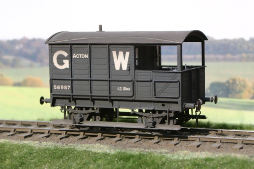
Twelve examples of the Great Western’s 13 ton AA7 brake vans were built between 1897 and 1898 to Lot 206 for working the company’s trains from Acton over the Metropolitan and (for a short stretch between Farringdon Street and Aldersgate Street) the Widened Lines to Smithfield – they were numbered in the series 56985-96.  Essentially they were a short version of the AA3 vans with a 9ft wheelbase, measuring 16ft over headstocks with a proportionally smaller verandah than the larger vans.

© Adrian Marks

It has been suggested by various authors that the AA7s must have been the among the first fitted brake vans on the GW because of the Smithfield meat trains, which included fitted Micas, but in reality, the perceived volume of meat traffic to Smithfield has been blown out of all proportion, and careful study of the relevant WTTs show that in fact the meat trains made up only a very small percentage of the traffic over the route as Smithfield was also the main general merchandise goods depot for central London and the City. To put things in perspective; in 1912, out of sixteen daily goods trains only four were scheduled for meat traffic, and of these, three were mixed trains of meat and general merchandise. Quite surprisingly, only one single trip each day was solely reserved for the conveyance of meat. It’s worth remembering that Mica’s were vacuum braked to convey chilled and frozen meat between Birkenhead and London at passenger-rated speeds, and it would have been the brake vans on those trains which were first vacuum fitted. It wasn’t until later, maybe much later (post-Grouping?) that vacuum braked stock was required on the Smithfiled trips.

The model is from Big Jim’s wonderful Connoisseur range, and the only major deviation I made was the addition of WEP compensation units rather than a solid chassis. GW paint from Precision, weathering from Humbrol and transfers from the HMRS. Glazing is 0.13mm glass, instanter couplings from CPL and sprung buffers from Slater’s.

This example was built to commission, and is in 0 Finescale, but I have a pair to build for Basilica Fields where meat traffic not only shuttles between Acton and Smithfield, but east from Smithfield to St. Katherine Dock via Basilica Fields on the (Middle) Circle Extension.

© Adrian Marks

No photoshoppery…well, just a little to get rid of a couple of specks of dust, but the colours and lighting is au natural care of the fat old sun.

Some 1600 ten ton open merchandise wagons to Diagram 03 were built by the Great Western Railway in four batches during the years 1904-5 and 1912. These wagons were a development of the Diagram 04 introduced three years earlier and incorporated a 4⅛” wider top plank bringing the internal height to 3’3″ which remained the basic standard for GW 10 & 12/13T opens in all future builds. At the same time the width was made wider by 6″ bringing the inside and outside dimensions to 7’7″ and 8′ respectively. Many, perhaps most, of the 03s were fitted with the Williams patent sheet supporter to aid the wagons sheets protect the merchandise when in transit.

I recently completed a commission for an 03, built from a WEP kit and this was given a light weathering as if recently built. The running number suggests that it is one of the final batch, and as the wagon will fit into a c1912 scenario, I think the degree of weathering is appropriate.

As these wagons were introduced in 1904 it would be reasonable to incorporate a small number in amongst the larger proportion of 4-plank wagons running on the Metropolitan Line between Acton, and Smithfields through Basilica Fields on the Extended Circle around to the GW depot at St Katherine Docks. Of course they will have S7 wheels whereas this has standard 0 Fine wheels.

I’m not too happy with the photo as the light was fading so I used some artificial daylight to help but it mucked the colours up and I couldn’t fix it to my satisfaction on the computer. If I get some decent mid-morning light before the wagon gets delivered I’ll upload some better photos and hopefully show the folded wagon sheet inside too.

This post is by way of a place holder for a subject which is proving difficult to crack…  that is:- how did the Metropolitan Railway arrange the switch and crossing work for their permanent way.  If the short and snappy title of the post leaves you a tad puzzled then the subject of this post is the way in which the Met. Rly. arranged the rails, chairs and timbers for the turnouts.  At this point, after more than six months of research into the topic, we have to say that we know very little about Met. Rly. turnouts in the period 1885-1905  and much of what we understand about the subject has been provided in anecdotal form – primary source material is noticable by its absence.

The recent comment by Kit Williams prompted me to look for a copy of the book which was mentioned in the first paragraph, “A History of the Metropolitan Railway – vol. 1”, (Bill Simpson, Lamplight Publications, 2003, isbn 1 899246 07 X).  First port of call when searching for railway titles is the “Railway Collection” of Hampshire County Council – a collection of circa 10,000 volumes which has its origins in the library of the Eastleigh Railway Institute.  The collection is housed in Winchester Library and the majority of the items are available for loan; Hampshire Libraries provides an on-line search facility which includes the railway collection, a couple of minutes work with the keyboard informed me that the required book was available “on-the-shelf”.

The photograph on page 28 is known to Adrian and I, we have a copy of the image from an unknown source.  Whilst the photograph is out of copyright we are not sure as to the situation regarding reproduction of this image and hence its absence from this journal.  Suffice to say that the photograph is one of only a handful of images of Met. Rly. turnouts in the pre-electrification era and hence is key to our modelling of that aspect of Met. Rly. permanent way.  For those who are interested in the subject, the London Transport Museum has an on-line photograph collection and one of those images shows the same junction from a different position.

So thank you to Kit for prompting a start on this subject….


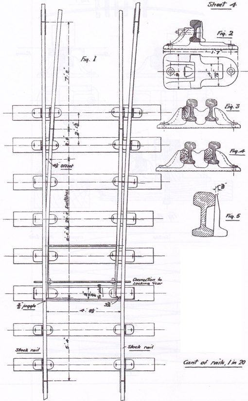
Part 1 of this topic introduced the background to the permanent way of the Great Western depot at Gun Street by way of a summary of  primary sources and an indication of the type of track to be found in the sidings of the depot. This post expands upon the summary  of part 1 by describing the PW and the Switch and Crossing fittings and by including some relevant drawings from the GWR Engineering  Society pamphlet “Some Notes on Permanent Way” (Harvie 1898).

To recap; the Gun Street depot was opened circa 1880 and at that date the permanent way of the Great Western “narrow gauge” could, maybe unkindly, be described as ‘lightweight’ with rails of 86lbs per yard (Bowler 1923). The damp and acidic atmosphere in the  Metropolitan Railway tunnels caused excessive corrosion and wear of the rails, in some locations the track deteriorated so quickly that the Metropolitan Railway replaced the rails every 2 to 3 years. Whilst traffic over the Inner Circle Extension was far greater than the traffic in Gun Street depot, the rail conditions were such that the shunting engines slipped frequently, and as a result the GWR had to replace the rails more than once in the 1880s and 1890s.

The GWR increased rail strength progressively with a rail of 92lbs per yard section in 1894, a 95lbs rail in 1897 and a  97 1/2 lbs rail in 1900. Apart from an increase in the width and depth of the rail foot from 86lbs rails to 92lbs rails, the sections  of the 92lbs, 95lbs and 97 1/2 lbs rails are very similar and difficult to distinguish in photographs. By the mid 1890s the original 86lbs rails in the Gun Street depot had been replaced by a stronger rail and the change in the dimensions of the rail foot dictated that the chairs (and sleepers) were replaced at the same time. By the mid 1890s the permanent way had been re-laid from the formation upwards and reflected contemporary GWR PW practice.

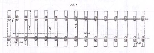
GWR plain track of the mid-1890s used 32ft rails of 92lbs per yard carried in cast iron chairs with 12 sleepers per rail length, except where the formation was soft, then an extra sleeper per rail length was introduced. Much of the ground in the vicinity of the the Inner Circle Extension, including Gun Street, was old marsh land, so naturally the GWR used 13 sleepers per 32ft rail throughout the sidings. Standard sleepers were 9ft long, of 10in x 5in section and made of Baltic redwood fir, the sleepers were treated with creosote before the chairs were fixed by fang bolts. The arrangement of a plain track panel with 32ft rails is shown below.

Sleeper spacing for plain track with 32ft rails and 13 sleepers, circa 1895

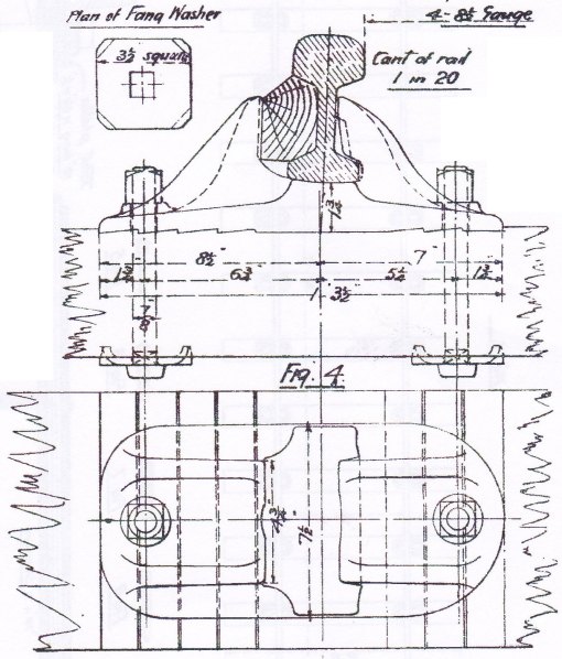
The GWR standard plain chair of the period was of cast iron and weighed circa 46lbs. Keys to retain the rail in the chair were made of oak or teak… and handed. A drawing of the standard chair, with fang bolts, nuts and washers, is shown below.

Standard chair for plain track, 92lbs and 95lbs rail, circa 1895

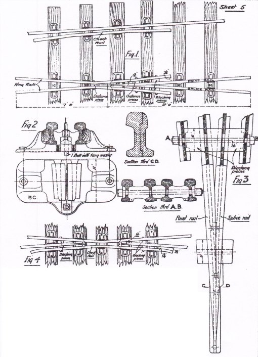
The arrangement of the common crossing for simple turnouts requires special chairs and fittings to hold the crossing vee and wing rails in alignment. The GWR had a range of special chairs for the various crossing angles and each chair type was used at a specific position relative to the crossing nose. In the 1890s those chairs were referred to as the 1C, 2C… 6C chairs although nomenclature changed later. At this time the chair under the crossing nose, referenced here as the 3C chair, was a casting – the nose of the vee slid into the casting and was retained by a vertical bolt through an extension of the nose. Some of the special chair types are shown below.

Arrangement of common crossing showing special chairs, distance pieces and blocking pieces

As with the range of common crossings with different crossing angles the GWR had a range of switches of different lengths. The switch rails varied in length according to the radius of the turnout… the greater the radius the longer the switch. In the period of Basilica Fields the switch blades were available in lengths from 9ft up to 20ft where the length is measured from the tip of the switch to the point at which the switch rail has attained the “4 1/2in offset” from the stock rail – the switch rail extends for 2ft beyond the “4 1/2″ offset” and the extra length is supported in the heel chair. The switches of a simple turnout are shown below.

Arrangement of switches showing switch rails, slide chairs and heel chairs

The next part of this topic is to cover the construction of some plain track for the sidings and the catch point where the sidings join the Inner Circle Extension of the Metropolitan ‘Main Line’.

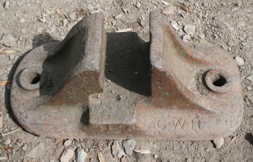
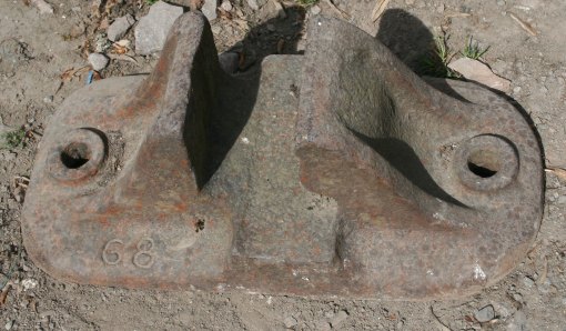
After publishing the first version of this post, and subsequent to the comment from Alan Woodward, I have been able to photograph an example of a chair as shown in Harvie’ s paper (drawing sheet 1, fig. 4 – illustrated above).  Of interest given the comments on this post and on a recent Quirky Query  is that the chair has recessed characters and the number “68” (which may refer to the “68d section”, 86lbs per yard, which was introduced in 1882).

GWR Chair similar to Harvie fig.4 showing "GWR"

GWR Chair similar to Harvie fig.4 showing "68"

Next Page »