Permanent Way


This post is by way of a place holder for a subject which is proving difficult to crack…  that is:- how did the Metropolitan Railway arrange the switch and crossing work for their permanent way.  If the short and snappy title of the post leaves you a tad puzzled then the subject of this post is the way in which the Met. Rly. arranged the rails, chairs and timbers for the turnouts.  At this point, after more than six months of research into the topic, we have to say that we know very little about Met. Rly. turnouts in the period 1885-1905  and much of what we understand about the subject has been provided in anecdotal form – primary source material is noticable by its absence.

The recent comment by Kit Williams prompted me to look for a copy of the book which was mentioned in the first paragraph, “A History of the Metropolitan Railway – vol. 1”, (Bill Simpson, Lamplight Publications, 2003, isbn 1 899246 07 X).  First port of call when searching for railway titles is the “Railway Collection” of Hampshire County Council – a collection of circa 10,000 volumes which has its origins in the library of the Eastleigh Railway Institute.  The collection is housed in Winchester Library and the majority of the items are available for loan; Hampshire Libraries provides an on-line search facility which includes the railway collection, a couple of minutes work with the keyboard informed me that the required book was available “on-the-shelf”.

The photograph on page 28 is known to Adrian and I, we have a copy of the image from an unknown source.  Whilst the photograph is out of copyright we are not sure as to the situation regarding reproduction of this image and hence its absence from this journal.  Suffice to say that the photograph is one of only a handful of images of Met. Rly. turnouts in the pre-electrification era and hence is key to our modelling of that aspect of Met. Rly. permanent way.  For those who are interested in the subject, the London Transport Museum has an on-line photograph collection and one of those images shows the same junction from a different position.

So thank you to Kit for prompting a start on this subject….


Basilica Fields is a 7mm model of a railway set within the context of the East End of London…  a “what if” railway with a supporting history which is sometimes somewhat different to the expectations of academics and historians of all persuasions.  Within the world of Basilica Fields there are several, separate, “scenes” which represent different railway locations in the vicinity of Bishopsgate – Artillery Lane is the first scene to be brought before the public gaze.  The railway history of Basilica Fields is set in late Victorian / early Edwardian days and this brings a pleasing benefit in that the model shall present railway services from up to seven railway companies running on the tracks of just one or two, or maybe, three pre-grouping railways.

The permanent way for Basilica Fields is built to S7 standards – 7mm scale modelling with a track gauge of 33mm, (Scaleseven track and wheel standards).  There is no “S7 equivalent” to buying a box of “O-gauge track” over the shop counter so all of the permanent way for Basilica Fields is hand-built.  As the S7 standards for track are generally independent of company….  and track has to be constructed to represent the permanent way of at least three pre-grouping companies (Metropolitan Railway, Great Western Railway and Great Eastern Railway)….  then this post describes the construction of plain track in a generic way.  Where the 7mm track has a feature which is company-specific then that feature is covered within the descriptions of the prototype permanent way; so for example:- the use of a jig to provide sleeper spacing is described here whilst the details of the sleeper spacing are to be found in the respective descriptions of Permanent Way.

So where to start?  Perversely, with the end product so as to explain the philosophy behind preparation of parts.

I have been making S7 track for at least five years and what follows represents my approach to achieving a consistent result and where the initial colouring of the components has been achieved before assembly.   The appearance of the track panels at this stage is “clean”…. colouring of components before and weathering after assembly is easier than assembly/laying/painting in place.  All of the weathering is to be done after the track has been laid and the techniques are to be covered in a separate post.

The sleepers are made from Lime and are of scale 9′ x 10″ x 5” dimensions.  The sleepers for Basilica Fields are supplied ready-cut from Perfect Miniatures.  The colouring process uses shoe dyes with IPA to let down the intensity of the dye and as a medium when the sleepers are immersed in the dye.  Much of the track of Basilica Fields is set in brick-lined cuttings where the sun shines on the track for just a few hours of the day, so the initial staining of the sleepers represents timber which has retained something of its original colour and yet appears to be damp and dirty.  The initial stain is a 10% by volume solution of the brown dye….  with several “dips” to build up the colour.  After the sleepers have attained a deep brown colour the damp and dirty colouration is applied by immersion in a solution of 10% brown and 10% black by volume.
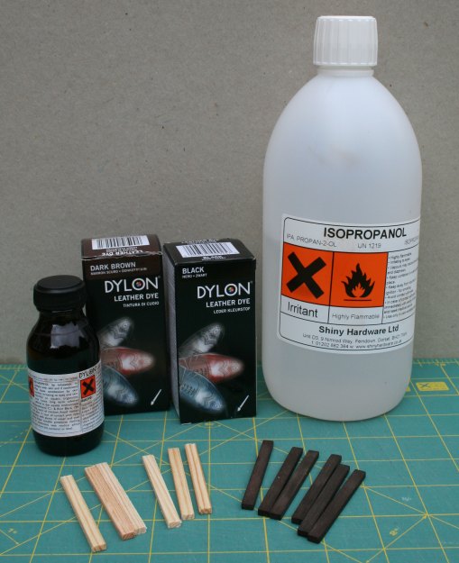
In the beginning - dyeing materials

The stain solution is made up in a plastic tub, the sleepers dropped in and the tub agitated (gently!) to ensure that the sleepers are covered and wetted all over.  After five minutes in the solution the sleepers are drained using a metal kitchen sieve (retained for the sole use in staining) and then left to dry on newspaper…  with the drying sleepers being “tumbled” occasionally to promote the drying process and to avoid a blotchy appearance.
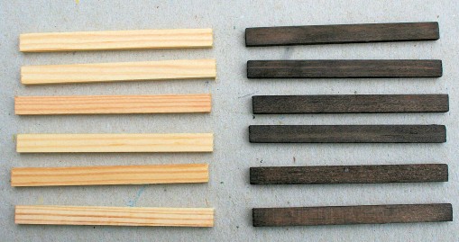
Sleepers - before and after

Now on to the chairs…  in this case the chairs are from the C&L Finescale range as being similar to those used by the GWR circa 1895, (see the drawing in GWR PW for Gun Street).  Enamel paints (Humbrol) are used for painting the chairs with the “dirt and weathered rust” colour from a palette of black, brown and gunmetal (33, 133 and 53 respectively).  The oak keys are then painted using a mix of  “track dirt” and “rusty rails” (Precision Paints).  Keen-eyed readers will spot that the chair sprue has chairs with keys to the left and chairs with the keys to the right….  this difference between “LH” and “RH” chairs is important when fitting chairs to the rail.
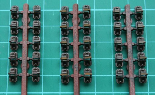
Painted chairs - rusty (left) and dirty keys (centre and right)

Sleepers are loaded into a jig which enables sleeper spacing along the rail to be replicated for each new panel; in this case all of the sleepers are the same width (GWR – 10″), where a track panel has wider sleepers at the ends then that increased width is accomodated within the appropriate jig (Met. Rly. – 12″).  Chairs are slid onto the rail, which is blackened chemically, with care taken to ensure that the keys are aligned correctly for the intended use of the track panel (and with the keys of the outermost chairs arranged so as to be “driven” towards the fishplates).  The rails are held at 33mm apart by S7 Group track gauges – available from the S7 Group stores and a benefit of group membership.

The chairs are fixed to the sleepers by Butanone which is applied by brush on eitherside of a chair where the chair touches the sleeper.  The chairs are moulded in ABS and that plastic is soluble in Butanone.  The solvent runs into the gap between the chair and sleeper, dissolves the base of the chair and the resulting ABS “gloop” gets drawn into the grain of the sleeper (by virtue of the solvent which has been absorbed by the timber).

The jig is a piece of 3/4″ chipboard upon which is fixed a distance piece cut from 4mm MDF – the MDF is 55mm wide and less than the length of the sleepers (63mm).  Thin, 1/16″, ply spacers are glued on top of the distance piece – the width of the spacers is such as to place the sleepers at the required centres. The sleepers extend beyond the distance piece so that an assembled track panel can be removed by raising all sleepers at the same time rather than sliding the panel sideways (if a sleeper sticks as a panel is slid sideways then that “sticky” sleeper can impart a twisting moment to the bond between chairs and sleepers).
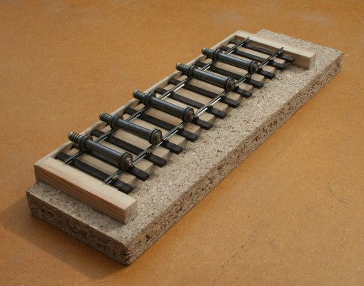
 

track jig with sleepers and rail/chairs/gauges

“Here is one I prepared earlier”…  a representation of a GWR track panel with 32′ rails, 13 sleepers and appropriate chairs and fishplates (as in the GW PW post referenced earlier).
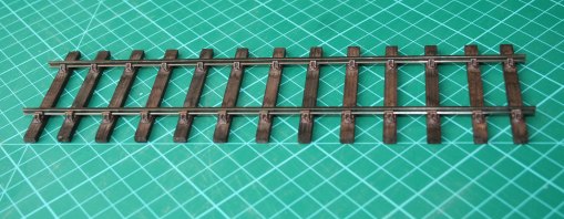
The final result - a representation of GWR track panel, 32'0" rails, 13 sleepers, circa 1895

One of the benefits of 7mm scale modelling is that parts are bigger and more detail can be included.  Exactoscale locking fishplates are fitted to the track here, these fishplates are moulded in ABS and hence provide insulation between rails.  Each moulding has bolt heads on one side, and nuts on the other side, of the moulding.  The light colour of the keys allows the placing of the keys to be seen with the outermost chair placed so that the key is “driven” towards the fishplate.
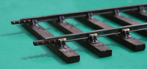
Completed track - fishplates and keys

Graham

Ref:- Quirky Query 2 – GWR PW in Victorian times

We left Quirky Query 2 with some photos of a GWR rail chair (in my care) and the question…  “is the chair an example of the type for the 86lbs rail of 1882 ?”.   None of the comments on that post have provided a definitive answer…  rather those comments have deepened the puzzle.  In the meantime, Adrian and I had concluded that the sidings in Gun Street depot were subject to frequent renewal and so the model shall portray the GW PW of the mid 1890s rather than of the early 1880s.  However, the comments to Quirky Query 2, combined with new photographs, suggested that there is more to the original post than was thought.  In taking this story forward, I am glad to acknowledge that the comments on QQ-2 awakened a recollection as to where I might find some contemporary material. A recent bright and sunny day provided the ideal opportunity to do some detective work and the results are presented here.

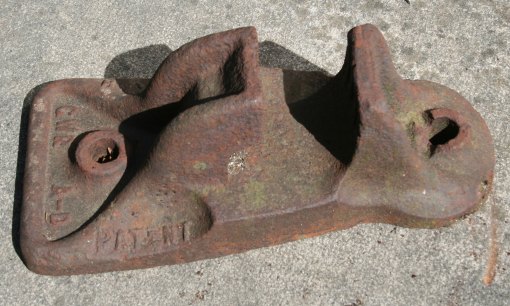
Our railway “heritage” sites provide railway historians with many opportunities to study artefacts from an earlier age and none more so than with bits and pieces from the railway infrastructure – in this case the simple rail chair.  At one particular heritage site an unknown person has “collected” examples of chairs from a range of pre-group companies….  and that collection includes a couple of chairs which are very similar to my example.  The photographs below show an example  of the type with raised rather than recessed lettering – just as predicted in a comment to QQ2.

The first photograph shows a side view of the chair – with the word “patent” visible in raised letters.

GWR Chair - 1

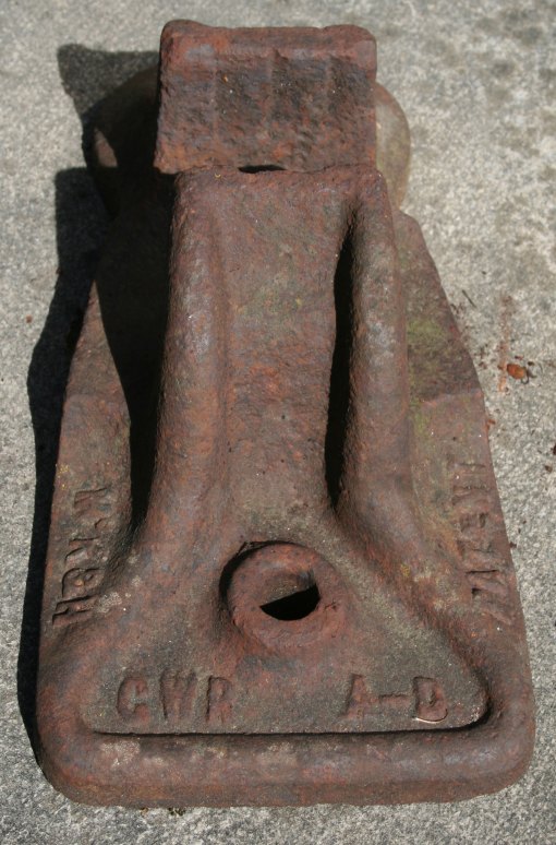
The second photograph shows an end view – with “GWR” and “A-D” in raised letters.  I hope that a reader can explain the significance of “A-D”.   In passing, note the grooves to the inner face of the far jaw…  a feature which is discussed later in this post.

GWR Chair - 2

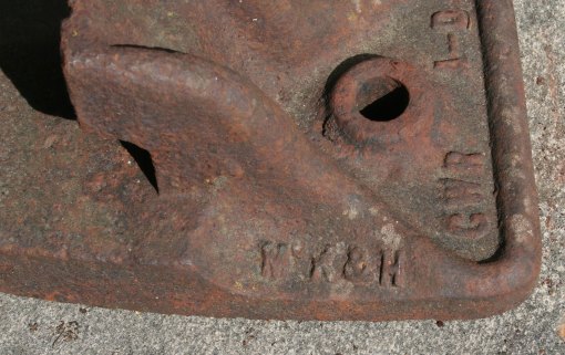
The third photograph is another side view – and shows yet more raised lettering,”Mc K & H” which I feel is likely to be McKenzie & Holland (a signalling contractor).

GWR Chair - 3

The Malvern Industrial Archeology Circle website offers an outline of the history of Mckenzie & Holland where the origins of the signalling manufacturer is recorded as “Thomas Clunes”, iron and brass founder of the “Vulcan Iron Works” in Worcester.  McKenzie & Holland as a company name dates from the mid-1870s which means that the chair in the photograph is post circa-1875.   What aspect of the chair is the subject of the “patent” is not yet known to me.

Returning to the chair in the original QQ2 post, the similarities between that chair and the casting above are very strong, the only significant differences are the lettering and the manner in which the lettering is represented – comments to QQ2 noted that raised letters are easier than recessed letters for cast items…  and that the “pattern” for the chair casting was likely to have been made as a metal item (from a wooden master with double shrinkage allowances).  In the absence of any information about the nature of either the “patent” or the business relationship for supply of castings – the possibility exists that the GWR bought the patent-rights from McK & H and thereby gained a metal pattern for the cast-iron chair.  Removal of the raised lettering on the metal pattern would be fairly easy – building up new lettering would be difficult and hence one can suggest that the new lettering was “engraved” into the metal pattern hence the recessed lettering on my chair.

As for the vertical grooves in the jaw, Harvie (1898) records that the GWR had been experimenting with spring clips as an alternative to oak or teak keys.  The relevant text refers to a circular spring clip being inserted into the space between the jar and the rail with the ends of the clip bearing on the rail.  Whilst not conclusive the grooves on the face of the jaw may be related to the use of such clips.

Unfortunately none of the above furthers the case for the original question…  however, the similarity of my chair to the McK & H specimen puts the likely date of casting as contemporary with the introduction of the 86lbs rail in 1882.

Graham

Ref:- The Permanent Way of the Great Western Railway for Gun Street depot (part 2)

Ref:- Quirky Answers – GWR PW Chairs

Many years ago I was asked to collect a “package” for a fellow S7 modeller…   he had won an E-bay auction and the buyer had requested collection for the “package” weighed around 90-100 lbs..  When my friend called to collect his “purchase” I was shown what I had collected –  two cast iron rail chairs.  One of the chairs was from the L&NWR and has no relevance to this journal.  The second chair was from the Great Western Railway and my friend suggested that I might like to retain the item and that is how I came to be the custodian of a (very) small part of GWR history.

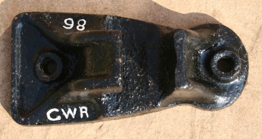
I  have tripped / fallen over the GWR chair so many times in the last few years without giving any thought as to the part which it might play in the  alternative world of Basilica Fields…  and ‘Quirky Queries’ owes its inclusion in this journal to yet another encounter between my toes and that immovable object.  Some weeks after the Permanent Way of the Great Western Railway for Gun Street depot (part 1) was written I came across the chair again and this time the lettering on the base attracted my attention.  There are several collections of railway chairs at different “heritage / preservation” centres and most of those chairs have raised letters / numbers on the top surface of the base.  In general, the letters /numbers give information about the relevant railway company, where and when the chair was cast plus an indication of the chair type (for example:- plain line chair, switch chair, crossing chair… ).  However, this chair does not conform to the norm for the only markings on the chair are “GWR” and “86”, markings which appear to have been recessed into the casting.

GWR rail chair - top view

GWR chair - three quarter view

GWR rail chair - side view

Now it is possible that the chair dates from a time when the “normal” expected details were not included on the casting.   However, the general size and shape of this chair suggests that it pre-dates the style of chair shown in the drawings of the Permanent Way of the Great Western Railway for Gun Street depot (page 2).

So, do the photos show a rail chair for the 86lbs per yard rail which was instroduced in 1882?

What do you think?

regards, Graham

[further information on this type of chair has been found and the topic is now continuing as a Quirky Answer ]

Part 1 of this topic introduced the background to the permanent way of the Great Western depot at Gun Street by way of a summary of  primary sources and an indication of the type of track to be found in the sidings of the depot. This post expands upon the summary  of part 1 by describing the PW and the Switch and Crossing fittings and by including some relevant drawings from the GWR Engineering  Society pamphlet “Some Notes on Permanent Way” (Harvie 1898).

To recap; the Gun Street depot was opened circa 1880 and at that date the permanent way of the Great Western “narrow gauge” could, maybe unkindly, be described as ‘lightweight’ with rails of 86lbs per yard (Bowler 1923). The damp and acidic atmosphere in the  Metropolitan Railway tunnels caused excessive corrosion and wear of the rails, in some locations the track deteriorated so quickly that the Metropolitan Railway replaced the rails every 2 to 3 years. Whilst traffic over the Inner Circle Extension was far greater than the traffic in Gun Street depot, the rail conditions were such that the shunting engines slipped frequently, and as a result the GWR had to replace the rails more than once in the 1880s and 1890s.

The GWR increased rail strength progressively with a rail of 92lbs per yard section in 1894, a 95lbs rail in 1897 and a  97 1/2 lbs rail in 1900. Apart from an increase in the width and depth of the rail foot from 86lbs rails to 92lbs rails, the sections  of the 92lbs, 95lbs and 97 1/2 lbs rails are very similar and difficult to distinguish in photographs. By the mid 1890s the original 86lbs rails in the Gun Street depot had been replaced by a stronger rail and the change in the dimensions of the rail foot dictated that the chairs (and sleepers) were replaced at the same time. By the mid 1890s the permanent way had been re-laid from the formation upwards and reflected contemporary GWR PW practice.

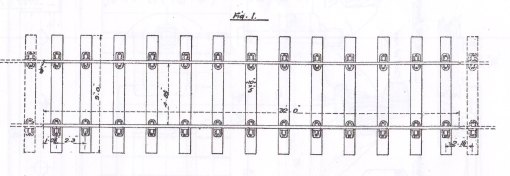
GWR plain track of the mid-1890s used 32ft rails of 92lbs per yard carried in cast iron chairs with 12 sleepers per rail length, except where the formation was soft, then an extra sleeper per rail length was introduced. Much of the ground in the vicinity of the the Inner Circle Extension, including Gun Street, was old marsh land, so naturally the GWR used 13 sleepers per 32ft rail throughout the sidings. Standard sleepers were 9ft long, of 10in x 5in section and made of Baltic redwood fir, the sleepers were treated with creosote before the chairs were fixed by fang bolts. The arrangement of a plain track panel with 32ft rails is shown below.

Sleeper spacing for plain track with 32ft rails and 13 sleepers, circa 1895

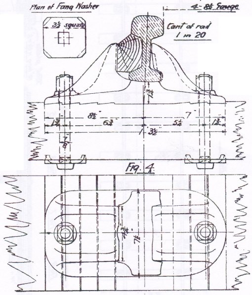
The GWR standard plain chair of the period was of cast iron and weighed circa 46lbs. Keys to retain the rail in the chair were made of oak or teak… and handed. A drawing of the standard chair, with fang bolts, nuts and washers, is shown below.

Standard chair for plain track, 92lbs and 95lbs rail, circa 1895

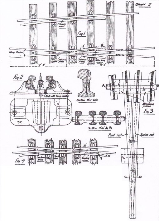
The arrangement of the common crossing for simple turnouts requires special chairs and fittings to hold the crossing vee and wing rails in alignment. The GWR had a range of special chairs for the various crossing angles and each chair type was used at a specific position relative to the crossing nose. In the 1890s those chairs were referred to as the 1C, 2C… 6C chairs although nomenclature changed later. At this time the chair under the crossing nose, referenced here as the 3C chair, was a casting – the nose of the vee slid into the casting and was retained by a vertical bolt through an extension of the nose. Some of the special chair types are shown below.

Arrangement of common crossing showing special chairs, distance pieces and blocking pieces

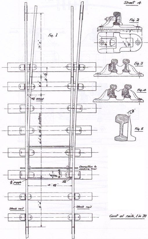
As with the range of common crossings with different crossing angles the GWR had a range of switches of different lengths. The switch rails varied in length according to the radius of the turnout… the greater the radius the longer the switch. In the period of Basilica Fields the switch blades were available in lengths from 9ft up to 20ft where the length is measured from the tip of the switch to the point at which the switch rail has attained the “4 1/2in offset” from the stock rail – the switch rail extends for 2ft beyond the “4 1/2″ offset” and the extra length is supported in the heel chair. The switches of a simple turnout are shown below.

Arrangement of switches showing switch rails, slide chairs and heel chairs

The next part of this topic is to cover the construction of some plain track for the sidings and the catch point where the sidings join the Inner Circle Extension of the Metropolitan ‘Main Line’.

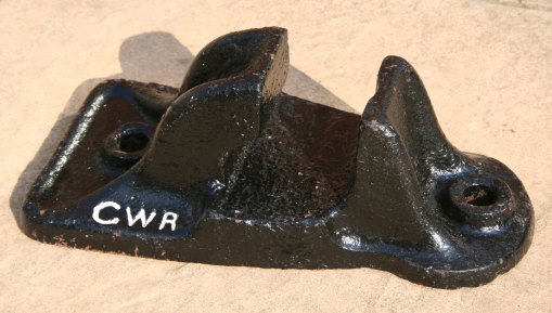
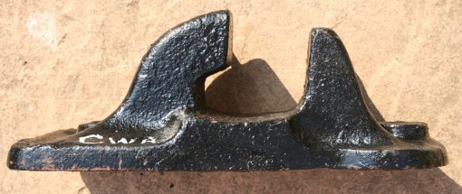
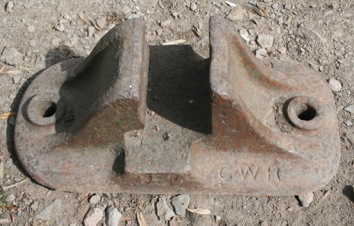
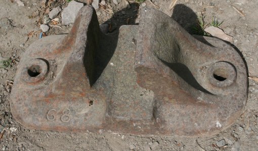
After publishing the first version of this post, and subsequent to the comment from Alan Woodward, I have been able to photograph an example of a chair as shown in Harvie’ s paper (drawing sheet 1, fig. 4 – illustrated above).  Of interest given the comments on this post and on a recent Quirky Query  is that the chair has recessed characters and the number “68” (which may refer to the “68d section”, 86lbs per yard, which was introduced in 1882).

GWR Chair similar to Harvie fig.4 showing "GWR"

GWR Chair similar to Harvie fig.4 showing "68"

Next Page »