During this advertisement break, Hokey-Pokey may be bought from the gentleman with the handcart at the front.

Victorian ice cream - a.k.a. Hokey-Pokey. Contamination often proved to be a serious health risk. Photograph ©Public Domain.

Victorian ice cream – a.k.a. Hokey-Pokey. Contamination often proved to be a serious health risk. Photograph ©Public Domain.

Consume at your own risk; the management refuses to accept the presence of fleas, torulæ, bacilli, lice, bed bugs, cotton fibres, bugs legs, straw, cocci, human hair or cat and dog hair in the ha’penny ices. Nor will the management be responsible if you contract scarlet fever, diphtheria, typhoid or diarrhoea  from partaking of these treats.

***

Activity Media‘s ‘Right Track’ DVDs have been helping modellers improve their techniques for almost 10 years. The latest in the series – number 19, believe it or not – takes us right back to the beginning with layout planning and design.

Unless your surname name is Freezer or Rice (oh, OK then, or Dunkley!) then chances are that at some point in the planning of your latest masterpiece you’ve sat with a blank sheet of paper in front of you and a waste basket full of scrunched up paper trailing behind.

Fortunately Paul Lunn’s name can be added to that list of luminaries of layout design, and coupled with Paul Marshall-Potter’s skilled eye for translating a design from paper to stunning model, this team presents a powerful addition to the Right Track series.

Many of us railway modellers are wedded to a scale and gauge, and this is the first sacred cow to be unceremoniously kicked over, and a compelling argument is put forward for choosing scale based on wants and needs from a new layout. Coupling choices are the next element to stand in the dock, and not just on the usual ‘play value versus scale appearance’ card we’re all so used to hearing, but instead based on how train length is affected by one type or the other, and how that impacts on our design. Thought provoking stuff.

With our comfortable world now turned upside down, we’re suddenly find ourselves within the habitat of the modeller; all so often our esoteric little hobby drags us away from family down into the shed at the bottom of the garden on a wet and windy night or up into the sauna-like humidity of a loft space in high summer. Not the always the best for harmonious household relations, and it needn’t be so. Based on a stylised representation of footfall though the house, we’re shown where hitherto unconventional sites for a ‘shelfie’ may in fact prove to be ideal and leave us feeling a little less like Johnny-no-mates.

On to the nitty-gritty; what do we want from a layout? Actually, what do we need might be the better question, and after writing out a checklist we’re building a quick mock-up from card and foam to see if all these elements of desire and necessity actually work together. Our perception of perspective, layout width and the backscene are briefly challenged – a foreshadow of things to come later in the programme.

Another chestnut roasted on the fire is the argument of prototype verses freelance trackplan, and Paul Lunn takes us though developing a layout based on a prototypical plan which ticks most of the boxes on our checklist. This is smartly followed up by the design of a freelance layout based on prototypical practice, but developed specifically to incorporate the choices we’ve made and rounds off the first hour of the DVD.

Moving from a two dimensional plan to a three dimensional layout can be a daunting task, and Paul Marshall-Potter describes how a very workable trackplan he had for a transition-period urban East End layout just simply didn’t ring true once he began the 3D process.

This revelation sets the scene for the next hour’s viewing where Paul Lunn takes the plan and turns it into three completely different but plausible alternatives;

  • A 1950s West country bucolic station which introduces us to the necessity of the overall visual balance of a layout
  • A 1980s aggregate works, in which the often haphazard placement of view-blocks are challenged, where features are moved to de-compact the view, promote sight-lines, and to make their inclusion and placement more logical. In addition, lighting and how to eliminate shadows from the backscene are considered.
  • Wharfdale Road where we revisit some of the earlier choices such as space, couplings, length of sidings and loops and the use of smaller prototypes to suit the layout footprint. Paul Lunn takes the original premise, converts it into a layout design, and then Paul Marshall-Potter adapts it to build the DVD’s project layout.

Again we revisit earlier themes and are shown practical examples of how to force perspective at the ends, the advantages of a natural eye-level viewpoint, how to control sight-lines at the entrance/exit of the scenic section and the effect of curved corners on the backscene.

Photograph ©Activity Media

Rounding this section off we also consider how a viewer’s eye is naturally drawn to the centre of the layout, and how the often-used half-relief gable ends of buildings – which look great head on, but rather silly from the side – can be diffused with tree lines to create a more convincing background.

With the second hour up we move to the inner sanctum where the crown jewels are kept; Paul Marshall-Potter’s two layouts, Bawdsey and Albion Yard. The former was originally built by Chris Matthewman in the early 1990s, and was based on 1930s practice in East Anglia. Paul discusses the changes he has made to bring the timeframe forward to the transitional period of the early 1960s, the weaknesses of the typical early 1990s construction elements such as open fiddle yards, segmented low backscenes with right-angled corners and how he’s overcome them.  Designing layout construction for transport is also touched on. Albion yard, on the other hand, was designed and built solely by Paul and  incorporates modern and some very forward-thinking elements, such as the long and high single piece printed backscene which extends beyond the scenic area into the enclosed fiddleyard for visual purposes.

All in all it’s a valuable addition to the Right Track range, and particularly if you’re at the beginning of a new project, or part way through one and you’re feeling jaded as it’s not working out as you’d hoped.

On being sent my gratis reviewer’s copy, I was told to tell it as it is; good or bad – don’t pull your punches. Despite not receiving my promised reviewer’s fee of a bacon sandwich (you owe me in sauce Mistah PMP), I thoroughly recommend this DVD to newcomers of the hobby and grizzled old hands alike.

When production of the 600 diagram 32 8-plank loco coal wagons ceased in 1902 the total stock of this type stood at 2047. It was a thoroughly modern fleet with the oldest being introduced only eleven years earlier, and all bar one were rated at 10 tons.

At the turn of the century there was widespread interest in high-capacity coal wagons with their significantly lower tare to capacity ratio over the traditional 10 ton wagon, and in 1900 Holden introduced an experimental 15 ton wagon to diagram 33. However the wagon didn’t find favour, and the following year the company hired a 30 ton capacity wagon from Leeds Forge & Co. for £1 10s 0d per week, initially employing it on the Parkston to Bishopsgate service before sending it over other parts of the system. The ‘truck of large carrying capacity’ was rejected by collieries as it couldn’t be fully loaded – and so never realised its full potential – and the single side door proved to be impractical for unloading, so the GER returned it to its makers.

Photograph ©Public Domain.

The first of the line, no.933 built in the spring of 1902. The rest of the batch were numbered 1 to 61 and were the only batch to be fitted with a form of Parker’s either side brakes (note the short brake lever) and the experimental large and very modern ‘squared’ letters and numbers.  A photograph of no.65 taken in early 1903 shows the more familiar large rounded letters. These wagons were fitted with Holden’s split ‘R’ type axleboxes from new. Photograph ©Public Domain.

While the company continued to make use of its 10 ton fleet, Holden designed a new all-steel wagon of 20 tons capacity (perhaps with an eye on the recently introduced N4 and N3 20 ton wagons on the Great Western), consulting with and receiving assurances from enough collieries that they would be accepted for loading to capacity.  Production of the diagram 46 wagons commenced in 1902 and proved to be highly successful – a 400 ton train saving 10% in tare weight and over 30% in train length.

So successful was the design that further batches totalling 901 examples were built each year except 1915 and 1917-1919 down to 1920, and in consequence 650 of the diagram 31 loco coal wagons built during the 1890s were converted to diagram 48 high-sided general merchandise wagons between 1904 and 1911.

Photograph ©Public Domain.

No 587 of the 1910 batch on 1 September of that year. This was the final Order to have the single brake lever acting on all four brake blocks, and from 1911 the Morton brake was fitted to new builds. The more familiar 1903 livery was applied down to, and sometimes beyond(!), Grouping.  Photograph ©Public Domain.

To details; the steel wagons were 21′ 6″ over headstocks, had a 12′ wheelbase and Holden’s split ‘R’ type oil axleboxes were fitted. The first batch were fitted with Parker’s ‘either side’ brake gear which wasn’t particularly fail-safe, and in time was removed. The second batch built in 1903 had a single lever on one side of the wagon acting on all four wheels via yokes – the cross-shaft extending half-way across the wagon where the inboard end was supported by a support post, and this design was continued well beyond the period covered by Basilica Fields, up to and including the 1910 batch ending with wagon number 690. From number 691 of 1911 the either side brake lever issue was resolved with the introduction of the Morton clutch which was applied to all new builds and in time retrospectively fitted to all earlier builds.

Modelling the Diagram 46 wagons

Fortuitously D&S Models include these loco coal wagons in the range, but need to be backdated to cater for the GER period.

Photograph ©2007 Adrian Marks

Here’s a shelf-queen by D&S which I started many years ago and have, shamefully, still not completed.  I do have a rather lame but legitimate excuse that the axleboxes provided in the kit were completely wrong for the GE period, and I only managed to source some of the ‘R’ type a couple of years ago (thanks Mick!). I suppose there’s no excuse not to finish it now, nor the other half dozen in the pile… Photograph ©2007 Adrian Marks

References

There are various GA drawings at the NRM in York, one for the experimental diagram 33 and three for the 20T wagon dated 1908, 1912 and 1914.

Drawing no. 11290, Loco coal wagon, 15 tons, 8 plank, 18ft. Date: June 1900. Stratford Order E51, diagram 33W

Drawing no. 16285, Loco coal wagon, 20 tons, 21ft 6ins. Date: January 1908. Stratford Order R63, diagram 46W

Drawing no. 18248, Loco coal wagon, 20 tons, 21ft 6ins. Date September 1912. Stratford Order M73, diagram 46W

Drawing no. 19554, Loco coal wagon, 20 tons, 21ft 6ins. Date 28 October 1914. Stratford Order H77, diagram 46W  for batches built 1916-1921.


Two years ago I left the series on GE coal wagons incomplete, not for want of information, but simply an oversight – a silly error as the drafts were already complete. Here then is the penultimate entry, and the final one will go live in a couple of days.

During the 1890s receipts for coal traffic into London via the GN & GE Joint Line were strong, and investment in coal became a priority in the Boardroom at Liverpool Street. In 1892 the Great Eastern Railway became the major financial supporter of the proposed Lancashire, Derbyshire & East Coast Railway (from which access would be gained via a junction at Pyewipe on the Joint) by sinking a quarter of a million pounds into the building of the new line, for which the Company was given two seats on the Board.

When the new line opened in 1896 the GER insisted that operations be concentrated between Chesterfield and Pyewipe, thus gaining unlimited access to all the collieries on the system. By the end of the century twenty five Great Eastern-bound coal trains came off the LD&ECR each week, and to bolster the company’s loco coal wagons for this traffic, between 1899 and 1902 six hundred 15′ long, 8-plank wagons were built to a new design.

Photograph ©Public Domain

Damping down the coal dust at Stratford a decade and a half after the curtain closes on Basilica Fields. In front of the rotary tippler and 800 ton capacity reinforced concrete coaling bunker (containing about one and a half days’ normal supply) sits a line of loco coal wagons made up of a diagram 32 8-plank, two diagram 31 7-planks, a further diagram 32 8-plank and what looks like a post-War diagram 80 timber-framed 8-plank. The medium-sized post-1903 lettering for wooden-bodied  loco coal wagons makes an interesting comparison with the large 24″ lettering applied to general merchandise opens. A T18 ‘Buck’ fusses in the yard. Photograph ©Public Domain

Rated at 10 tons, the top three planks ran the length of the wagon over the top of the side doors, and as the steel floor precluded a curb rail, a length of timber was attached to the side of the solebar onto which the door hinges were mounted.  The steel underframe was the standard Stratford design with a 9′ 0″ wheelbase, and a single brake lever actuated two brake blocks on one side of the wagon.

Finished in the standard grey livery with white lettering, the 1899 wagons had separate oval maker’s and load plates, but from 1900 a combined rectangular plate was fitted to new builds. The 1902 wagons may have been out-shopped with the medium-sized square lettering (I’ve not yet found a photo to confirm or deny), but over time all were given the post-1903 medium-sized rounded letters.

Photograph ©Public Domain.

The Great Eastern bought vast quantities of coal when prices were cheap, building huge mazes out of the  stacks which waxed and waned in size as supplies increased and dwindled. At March the coal stacks even crossed the sidings at peak capacity. On a dull, dank, and thoroughly dingy 23 October 1911 two diagram 32 loco coal opens are parked nearest the camera on the south side near Norwood Drove. Photograph ©Public Domain.


Sample numbers included 977, 1416, and 1978.

Modelling the wagons

I’ve not yet located the GA for these wagons, but the type is ripe for utilising an etch for the standard GE wagon underframe, and a resin casting to the wagon body.

In my original plan, the time-frame for Basilica Fields was going to span the early 1900s to circa 1915,  but somewhere along the line I dialled both ends backwards which means that the four classes of engines featuring in this entry will no longer play a part as their presence in an 1890s/early 1900s setting is an anachronism too far, even for my pet cat, Schrödinger. However, one or two of them may make an appearance elsewhere down some diverse branch of the Basilica Fields multiverse (but enough of that wibbly-wobbly timey-wimey stuff for now) so I’ve included them for completeness.

Upon James Holden’s retirement in December 1907, the position of Locomotive Superintendent was passed to his son Stephen Dewar, a decision which privately infuriated Frederick Russell, head of the Locomotive Design section at Stratford Works, who felt the position should have been offered to him. And not without good reason, for he was directly responsible for many of the designs attributed to James Holden such as the P43 4-2-2 Single, the famous Claud Hamilton 4-4-0 and the infamous Decapod 0-10 0T. However, nepotism won the day, and S.D. Holden took up the position in January 1908.  In the end it worked out for the good; Stephen Dewar’s tenure was short and his contribution to locomotive design fairly light (although he patented many inventions while at Stratford), much of the work under his reign can be attributed to  Chief Draughtsman E.S. Tiddeman, a long-term Stratfordian, who maintained continuity and ensured development of the Great Eastern style. Russell’s career took a different path – he was later promoted to  Superintendent of Operations by General Manager Henry W. Thornton, and was instrumental in devising and implementing the famous suburban Jazz services.

The Y65 Class

The last of James Holden’s revised version of the Worsdell M15 class was released to traffic on 18th June 1909, a full eighteen months after his retirement.  Holden Sr. had left the Great Eastern Locomotive Department in a tremendously strong condition, and it wasn’t until 20th July 1909 that the first locomotive built under Stephen Dewar’s tenure was put into revenue-earning service. The Y65 class 2-4-2Ts were intended to both replace the last of the pre-Worsdell o-4-4 tanks class and to free up for other duties the rusticated members of the E22 class which pottered up and down the lightest of GE branchlines.

Photo ©Public Domain

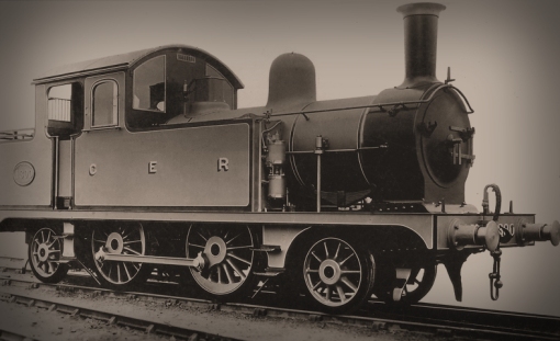
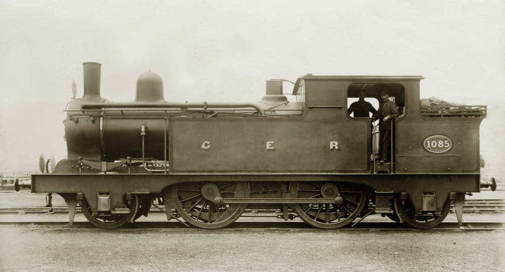
The prototype Y65 no.1300 posing in the photographic French grey (the ultramarine undercoat) livery with black borders and white lining. Most of the features mentioned in the main text can be seen; the brass-rimmed stovepipe, the dome on the back ring of the small boiler, the four-column Ramsbottom valves over the firebox, the large cab and huge quantity of glass – the tops of the front and rear windows following the profile of the high-arc roof, the brass ventilator, cab doors and coal rails on the bunker. Photo ©Public Domain

Letter Account Y65 consisted of two engines, and following on from the introduction of no.1300, no.1301 was released to traffic six days later on 26th July 1909. It’s certain that James Holden followed the career of his son, so must have looked on with amazement at the non-standard nature of this first locomotive which was an anathema to his legacy; a smorgasbord of old, new and seeming indecision. The uniquely sized 15” x 22” cylinders  were driven by Stephenson’s link valve-gear with slide valves in a geometry similar to the T18 class, the non-standard small diameter boiler measured just 3′ 11½” over the clothing and was pressed to a working pressure of 160p.s.i. With 3’6″ radial and 4′ 10″ driving wheels, the engines’ nominal tractive effort was 11607 lbs.

Stylistically the Y65s were a scaled-down M15 crossed with an E22 and topped-off with a capacious (some might say disproportionately large) high-roofed cab, mirroring the Great Eastern Railway’s express and goods locomotive policy of the new century, and set a precedent for future tank engine designs. These small radial tanks quickly became known as the ‘Crystal Palaces’ due to their not inconsiderable acreage of glass.

The water capacity of the small side tanks was 1000 gallons and the bunker held just two tons of coal.  The Worsdell-style dome was seated on the rear rather than the front ring of the boiler, and it’s difficult to understand the reason why four-column Ramsbottom safety valves were fitted when Stratford had always been – and would continue to be – satisfied that two-column valves were sufficient on boilers rated up to up to and including 160p.s.i. This anomaly was compounded by placing the valves over the firebox, in the manner of the two-column type, and implies that any safety concerns didn’t stretch as far as having the fireboxes stayed. The chimney was also unique, a kind of halfway-house comprising of a standard GE steel- fabricated stovepipe to Dia.1 with a brass rim of the type fitted to the contemporary large passenger engines. The Westinghouse pump and ancillary equipment, continuous handrails with integral Holden blower, cab controls, 1882 parallel-shank buffers, and whistle, et cetera, were all standard GER fittings.

Photo ©Public Domain

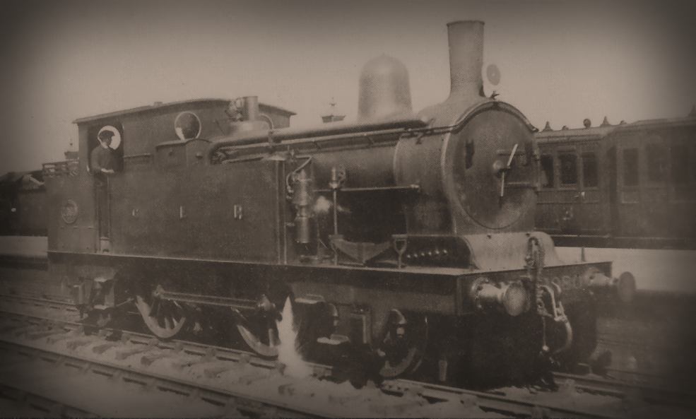
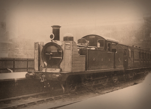
Having done the rounds on the lightly laid branch lines of East Anglia, many Y65s ended up back in the London District, several of which were converted for compressed air operated push-pull services. No.1304 was the second fitted with the equipment which was based on the LB&SCR auto gear. The converted Y65s had a second Westinghouse pump fitted to the front of the LHS tank along with extra Westinghouse hose connections and a couple of electrical connections on the rear bufferbeams, one of the latter can be seen running along the rear of the valance to the cab door. For the auto services increased coal capacity was needed, so an extra four rails have been added to the bunker. No.1304 stands at Seven Sisters in 1921 in a very tired and grubby blue livery. Most Great Eastern locomotives had by this time been repainted in the wartime grey livery after Stratford’s stock of blue paint had been requisitioned by the Admiralty in 1915. Curious to see the front RH buffer is of the 8-bolt tapered variety, while the LH buffer is still the old 1882 parallel type. The arch-topped front and rear windows of the A67 batch differentiate between the majority of the class and the two prototypes. Photo ©Public Domain

New features which would become standard on future GER tank engines included a  brass ventilator at the top of  the front weatherboard, and half-height coal bars to protect the large rear windows. Two coal rails were fitted from new to bring the coal capacity up to 2 tons, S56-style cab doors increased the comfort of the crew, and intriguingly, as the class clearly wasn’t intended for London District duties, destination brackets were fitted to the smokebox door and bunker rear.

As nos. 1300 and 1301 were being built, an order was put in for a further ten locos, and nos. 1302 – 1311 to Order A67 were released to traffic between 2nd November 1909 and 28th January 1910. This new batch of radial tanks were identical to their two predecessors with one exception; whereas the top of the front and rear windows on nos. 1300 and 1301 followed the contour of the roof, those on nos. 1302 – 1311 were the same shape as the windows on the cab side sheets.

The class were initially allocated across the GE system and sub-shedded at Buntingford, Saffron Walden, Ramsey, St Ives, Stoke Ferry, Aldeburgh, Hadleigh, Braintree and Maldon. Much has been written on the unpopularity of the class, but I believe the majority of this stems from rehashing the offhand nature of their entry in the RCTS Vol.7 (1964). Earlier histories such as Aldrich (1944) had nothing bad to say about them, simply remarking that they would have been improved if rebuilt with a larger boiler.

Photo ©Public Domain

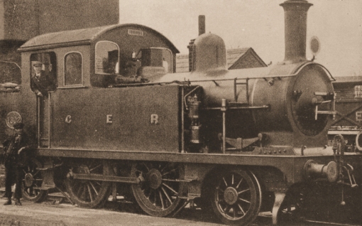
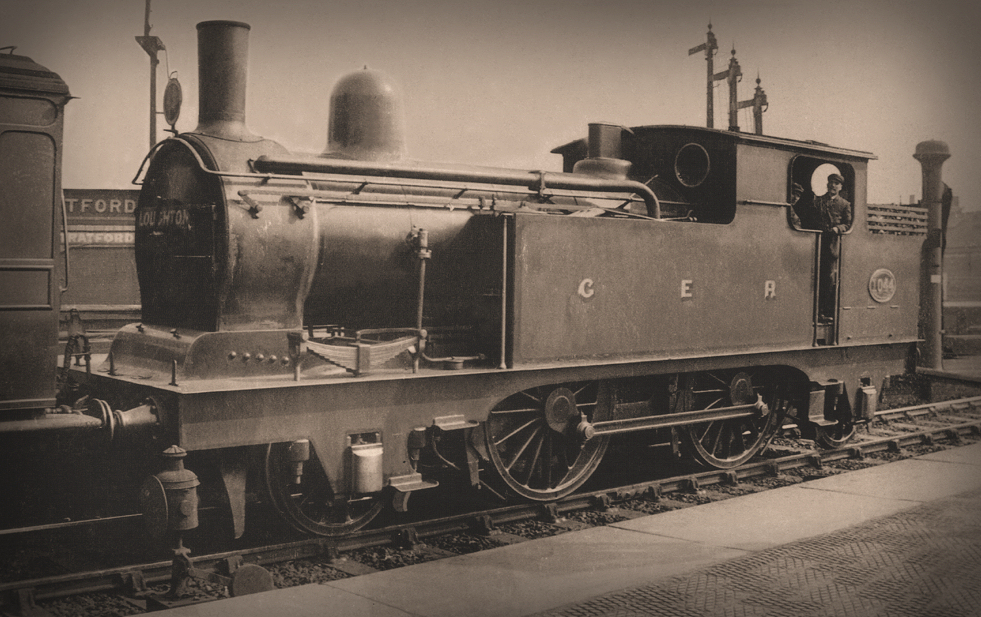
On release to traffic at the end of 1909, no.1302 – the first of the A67 batch – was sent to Buntingford, replacing no.1301 which was allocated to Colchester for working to Walton. Locomotives shedded at Buntingford were fitted with a small steam-raising stop valve so that at night they could operate a pump to raise water from a nearby well to refill the supply tank. This might account for the small ladder on the side of the boiler. A conical re-railing jack rests on the tank top. Despite being in the suburban timetable, there were never any destination boards produced for Buntingford. Photo ©Public Domain

Indeed, at Buntingford, the only allocation within the Stratford district and which hosted no.1301 from its release to traffic in July 1909 until replaced by the newly-constructed no.1302 in December of that year, the class proved to be very popular. Aside from the crews’ appreciation of the covered footplate, their ability to haul eleven six-wheeled coaches over the relatively steep gradients of the tortuous 13½ mile long branch with ease earned them their approval. Neither was this feat unusual; in later years Frank E. Wilson witnessed one of the class haul a pair of Gresley Quint-Art sets from Palace Gates to Liverpool Street and the smartly-timed service to Enfield.

In April 1913, no.1302 was sent to Southend to trial two-carriage trains in the newly-expanding residential area of Southend, stopping at a number of proposed halts - a pre-courser to the auto-train trials the following year. The experiment was short-lived and no.1302 is seen here later the same year back in the East End on a Canning Town service with six-four-wheeled suburban carriages. The two green discs with white rims indicate the train originated at Victoria Park. Photo ©Public Domain

In April 1913, no.1302 was sent to Southend to trial two-carriage trains in the newly-expanding residential area of Southend, stopping at a number of proposed halts – a precursor to the auto-train trials the following year. The experiment was short-lived and no.1302 is seen here later the same year back in the East End on a Canning Town service with six-four-wheeled suburban carriages. The two green discs with white rims indicate the train originated at Victoria Park. Photo ©Public Domain

It’s also interesting to note that the three remaining pre-Worsdell 0-4-4T classes they were supposed to replace remained in service and continued to be withdrawn at a slow pace, the last of which survived until the end of 1913. Concurrently the Y65s began to appear on services in the Stratford District, some of which would later include the Great Eastern’s early push/pull services.

Modelling the Class

Connoisseur Models once produced a 7mm kit of the class (strictly speaking the A67 batch), and I was fortunate enough to buy the penultimate one before they all sold out. I was going to run it under the same excuse I have included the E22 class – i.e. occasional through trains from Buntingford, but my self-imposed temporal constraints have now put paid to that idea. There is, however, a strong possibility that No.1302 will eventually surface elsewhere in the Basilica Fields meta-universe.

I have to admit I’m rather fond of this class and its quirky style, and for me their introduction heralded the end of all that had gone before; La Belle Époque of the Great Eastern Railway had come to an end and nothing would be the same anymore. Stratford was entering a modern mechanised age where there was no place for the breathtaking, bewitching, beguiling, or beautiful; new locomotives appearing from the Works would now be big, bold, brash and brutish.


The G69 Class

Increased demand on the London outer suburban services by the end of the Edwardian period prompted the need for more frequent and heavier trains. With the exception of the single experimental 12-wheeled bogie suburban carriage set on the Enfield line, all suburban trains were still made up of close-coupled 4-wheeled carriages built between 1885 and 1905. During the first half of 1910, drawings of eight- and nine-coach sets of 48′ 3″, 50′ 0″ (reflecting the design of main line stock) and 54′ 0″ long (twice the length of the 4-wheelers) eight-wheel bogie carriages were prepared to determine the best way forward.

Photo ©Public Domain

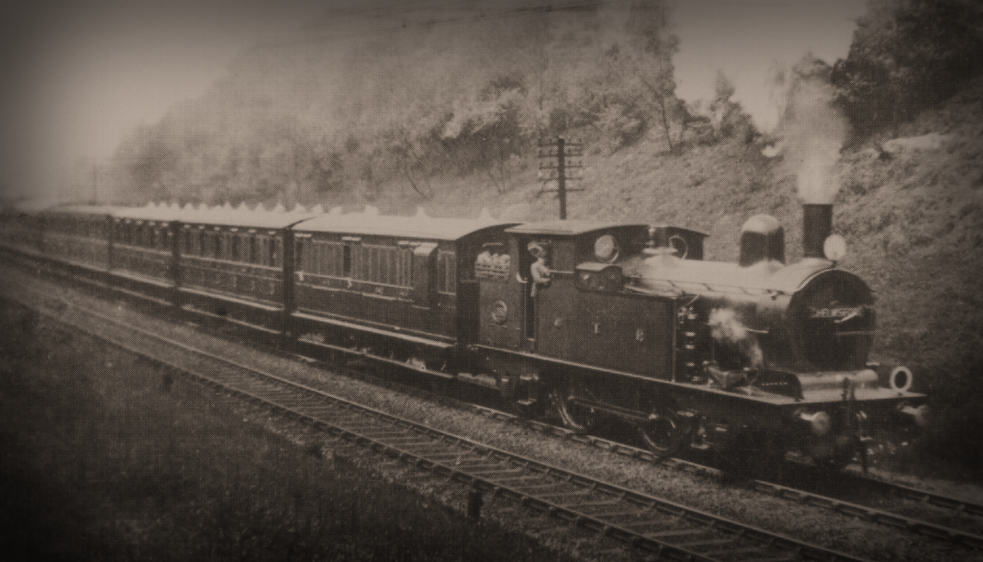
One warm Sunday in June on Brentwood Bank, no.63, resplendent in photographic grey livery, poses with the first of the new suburban bogie sets for the Loughton – Epping service. The large cab looks well-proportioned on these larger 2-4-2Ts with their high tanks and busy boilers. The four-column safety valves in the forward position and the parallel brass-rimmed chimney are prominent. The carriages are as follows: Dia.542 bk3rd no.333, Dia.236 1st/3rd composite no.7, Dia.104 1st no.10, Dia.300 2nd no.92, Dia. 300 2nd no.94, Dia.300 2nd no.97, Dia.237 1st/2nd composite no.6, Dia.542 bk3rd no.334. The set was close-coupled with a break point between seconds nos.94 and 97. Photo ©Public Domain

By the end of the year Stratford had settled on eight-carriage 54’0″ sets to the same design as the contemporary 50’0″ main line stock. These were designed to carry 808 seated passengers with up to half as many again standing, and, crucially, weighed 50 tons more than the comparative 4-wheeler sets. Four sets were completed in 1911 and a further ten were in service by 1914, all performing duties on the Loughton – Epping – Ongar line. Of course, the increased weight of the trains required more powerful locomotives and Stephen Holden chose to dust off his father’s revision of Worsdell’s M15 design, which had proven to be both reliable and capable for many years, and develop it for modern requirements.

The first of two batches of ten, numbered 61-70, formed Order G69 and were released to traffic between 3rd May and 30th June 1911. They took their numbers from a Neilson & Co.-built batch of Adams’ London Suburban 0-4-4 tanks, the No.61 class, which had been delivered in 1875-6, the last of which had already been added to the duplicate list and prefixed with a cipher.

Photo ©Public Domain

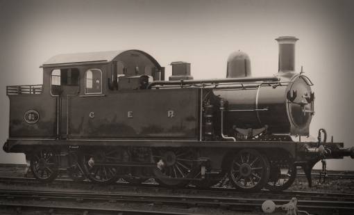
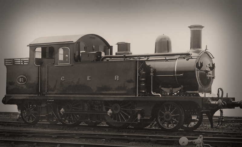
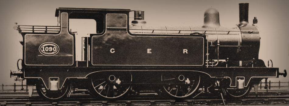
No.61, the first of the class, poses newly shopped in ultramarine blue, the vermilion lining not visible due to the limitations of the orthochromatic emulsion. Three coal rails were fitted from new, and unlike similar photographs of new G69s posed in grey, the running number is not repeated on the lined-out toolbox. Photo ©Public Domain

The second batch of ten to order A71 and numbered 1-10 entered revenue-earning service later in the year between 17th and 29th November. The 2-4-2T was the second Great Eastern locomotive to carry the prestigious No.1 works plate, the previous bearer being the first of S.W. Johnson’s 2-4-0 ‘Little Sharpies’ built in 1867 and remarkably still in service (and, incidentally, the last to be withdrawn in 1913), having been put on the duplicate list on the 1st January 1911 and its running number prefixed with a zero.

The G69 class were fitted with a brand new type of boiler, the same size as the M15s, but pressed twenty pounds per square inch higher at 180p.s.i. They had a sloping rather than a flat grate and were fitted with four-column Ramsbottom valves placed over the back ring of the boiler. Visually the biggest impact was the addition of the high-arched Y65-style cab (or, strictly speaking, the A67 cab) which appeared rather handsome and well-proportioned on these larger engines. There was a 10cwt reduction in coal capacity to 3 tons, but slightly higher side tanks gave an increase of 250 gallons to 1,450 gallons.

The engines had parallel built-up chimneys (and as passenger engines were topped off with brass rims) of a visually similar design to the tender engines introduced from 1898, with the exception that the base was slightly shorter. However, internally the chimneys were very different; all the chimneys on the larger engines, with the exception of Decapod, were tapered inside the casing and had cast iron petticoats (designated Diagram 2), whereas those on all the tank engines from G69 onwards were parallel inside (designated Diagram 3).

Photo ©Public Domain

Eight days after entering service, no.61 is photographed on 21st May 1911 at Liverpool Street with the unique 12-wheel bogie suburban set (with eight wheel bogie brake thirds at each end) built in 1900 for the Enfield line and described in the entry on the R24R class. At least engineers standing on the running plate testing the performance of the boiler had tall timber shelters by this time, their predecessors twenty years earlier had no such luxury, just a low shelter to stop them from falling off. Photo ©Public Domain

All twenty of the Westinghouse-braked engines were fitted with condensing apparatus for the London suburban duties. However, unlike the M15s, the vent pipes were situated on the tank tops outside the cab, pre-empting their position on the future L77 class 0-6-2Ts. One other visible difference contributed to the busy nest of rods and pipes on top of the boilers; on the M15 160p.s.i. boilers, injector steam cocks were mounted on top of the boiler back inside the cab, but on the 180p.s.i. boilers the same cocks were mounted near the dome with control rods leading back to the cab.

Modelling the Class

Laurie Griffin’s F6 kit is the LNER classification for the GER G69. It’s an upgraded version of the old Shedmaster kit, and with care produces an accurate model.


The M15R Class

With the first ten G69s entering service, the opportunity was taken to up-rate a number of the 1903-1909 series of M15s with the sloping-grate G69 180p.s.i. boiler, and to differentiate these locomotives from the earlier 160p.s.i. flat-grate rebuilds they were assigned the classification M15R or M15Rblt.

Photo ©Public Domain

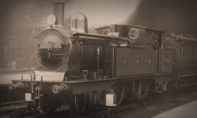
No.110 was rebuilt as an M15R in August 1913. The LH side injector valve is visible behind the dome, and the rimmed parallel chimney and four column safety valves in the forward position distinguish it from the M15 class engines. By the time of this photo, the old flat-dished smokebox door, which was prone to heat distortion, has been replaced with Alfred Hill’s heavier type. Eight-bolt tapered buffer housings have been fitted. Photo ©Public Domain

As noted above, the first G69, no.61 was released to traffic on 3rd May 1911, and one month later M15 no.104 entered Stratford Works for a General overhaul and to be rebuilt.  Four months later, on 9th October, both it and no.103 (which had come into Works two days after no.104) re-entered revenue-earning service as M15R class engines, the first of an eventual 30 members of the class. The vast majority of these rebuilds were completed over the next three years, and all bar one completed by 1916. No.188 finally re-entered service in June 1920 having languished in the sidings at Stratford since the end of the Great War.

Visibly there were few differences between the M15R and the 160p.s.i. M15s; the M15Rs had sloped instead of flat grates, G69-style parallel chimneys with brass rims instead of stovepipes, four-column safety valves seated on the back ring of the boiler instead of two column valves over the firebox, whistles mounted on the cab front instead of the valve seat, and the injector steam cocks mounted behind the dome instead of inside the cab.  The rebuilds retained their 1200 gallon side tanks and 3½ ton capacity bunkers.

Photo ©Public Domain

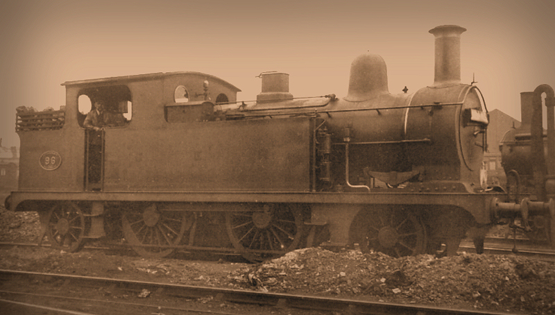
No.96 was converted to M15R in October 1911 and still carries the original smokebox door and 1882 parallel buffers. The RH injector steam cock on the boiler with the long control rod and pipe is is much more visible on this non-condensing member of the class. Somewhat intriguingly it has what appears to be a steam-raising stop valve in front of the dome, which suggests it may previously have been sub-sheded at Buntingford, though I have no record if it there.  Photo ©Public Domain

Twenty of the rebuilds were non-condensing engines, but six of these gained the apparatus during their rebuilding which indicated their anticipated duties. In his article ‘Improving Buckle’ Lyn Brooks suggests that the only mechanical difference between the M15R and G69 classes was the size of shim placed between the eccentric straps and rods in the link motion.

Visual differences between the M15 and M15R classes soon began to blur, a process which years later would eventually end with just the running number giving away the classification; in 1913 it was decided that engines and boilers were no longer paired for life, and the following year, once production of the 160p.s.i boilers ceased, G69 sloping-grate 180p.s.i. boilers began to be fitted to the 1903-1909 series of M15s with new four column valves de-rated to 160p.s.i. and placed in the forward position over the back ring. With the exception of No.798, which received a brand-new but de-rated 180p.s.i boiler in 1920, 160p.s.i boilers removed from the 1903-1909 series were set aside for surviving members of the three batches of M15s built during the 1880s – the first three of which had been withdrawn in 1913.

Photo ©Public Domain

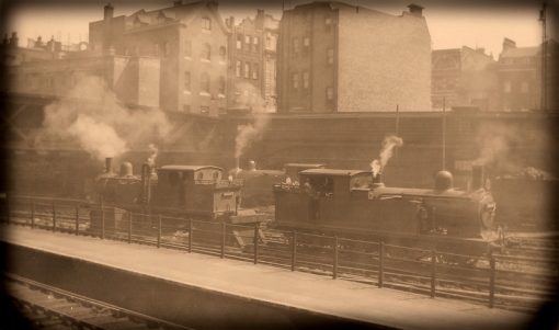
With the imposing Skinner Street bridge behind, 2-4-2Ts contribute to the smog as they wait their turn at Liverpool Street station. At the back a C32 class, at front right an unidentified 1903-1909 series condensing M15 class and on the left no.76, a condensing M15 with a 180p.s.i. boiler with four-column safety valves in the forward position and de-rated to 160p.s.i.  Neither the East nor West Side signal boxes had a full view of the domain they controlled so each had an extra ‘observation box’  located at the ends of platforms 4/5 and 14/14 respectively. The driver of the unidentified M15 lets off a sharp whistle and is looks towards the East Side OB indicating he is ready to move onto the waiting carriages in platform 13 for the next down outer suburban service. Photo ©Public Domain

At 53t 19cwt the M15Rs weighed 2 tons 6cwt heavier than the M15 class but 2½ tons lighter than the G69 class, although the tractive effort was identical to the latter.

Modelling the Class

The LNER classification for the GER M15R was F5 and both Connoisseur Models and Laurie Griffin can supply kits for the class, though third party castings from Laurie, Ragstone or Alan Gibson would be needed to backdate the kit to the GER period.


M15 with G69 Boiler and Large Cabs

In 1912 a hybrid conversion resulted in this rather convoluted classification for two locomotives, nos. 789 and 790.  Post-rebuild they were to all intents and purposes members of the M15R class, retaining their original 1200 gallon side tanks and 3½ ton capacity bunkers, but were  fitted with G69 cabs. Both had been built as non-condensing M15s in 1904 under Order D58 (no.790 being the second member of the class to carry that number, the previous bearer being renumbered no.800 in 1892), and both received condensing apparatus on being rebuilt. One interesting facet of this hybrid class was that like the M15 and M15Rs the condensing vent pipes were located inside the cab so projected through the roof. However, whereas the other locomotives had a sizeable stub protruding from the shallow-arc roof with the top of the pipe cut away horizontally, the top of the vent pipes on nos.789 and 790 were almost flush with, and contoured to match, the profile of the G69 high-arc roof.

Photo ©Public Domain

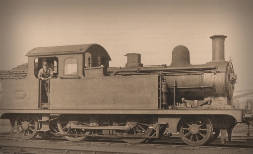
Hybrid no.789 looking very down-at-heel rests at Stratford. As can be seen, it is, to all intents and purposes an M15R with the G69 high-arc cab. From this angle the top of the condensing vent pipe can be seen almost flush with, and profiled to the shape of the roof. There’s an interesting riveted patch on the smokebox which I’ve not seen elsewhere. Photo ©Public Domain

It’s not known why nos. 789 and 790 were converted in this hybrid manner, but they brought the total number of conversions to thirty two.

One final, and somewhat intriguing comment about the M15-M15R and G69 classes is that the side tanks and bunkers had 2”x 2” angle around the bottom edges, flush-riveted to the running plate. The feature was common on earlier tank locomotives, but these and the T18’s were the only tank engines built after 1885 to retain the feature.

Modelling the class

Jim at Connoisseur Models sells an add-on pack of etches to convert his F5 kit into the F5/6 hybrids.

Photo ©Public Domain

The other hybrid, no.790 also looking very scruffy, although apparently with a new or reconditioned smokebox and chimney. Although the GER classified these two engines separately, the LNER somewhat confused by their nature, lumped them in with the G69s and classed them F6. British Railways saw sense and later reclassified them both F5. Photo ©Public Domain

To round off the 2-4-2T saga, I suspect that no more than a handful of Great Eastern Railway locomotives were captured on film during the pre-Grouping period. However, In October 1920 M15R no.96 was fitted with the experimental Regan electro-mechanical train control system and underwent trials on the Fairlop Loop. In addition to the automatic stop device, the right hand side trailing radial wheel was fitted with a speed control. The Great Eastern had already trialled the Sykes (SYX) train control system on the Palace Gates and Ongar branches, fitting the control gear to G69 no.66, part of which was designed in-house and patented by E. S. Tiddeman. The Regan system didn’t find favour with the company and the trials progressed no further.

Fortuitously the rushes survive in the Pathé newsreel library, and an article on the trials was published in the November 1920 issue of The Railway Magazine, illustrated with photos, possibly stills from the film. The article notes that those present included the inventor Mr J. B. Regan, Mr J. H. Thomas M.P., various chief officers of the GER, signal engineers and experts from several railway companies, and representatives of the technical and general press.

http://www.britishpathe.com/video/unknown-celebrities-at-inauguration-of-new-train-l

It’s a fascinating snippet for not only the railway element of seeing a Great Eastern locomotive at work on home turf in this period, but in terms of fashion, especially the wide range of hats, from the Bowler and Homburg, to the Fedora, down to the various styles of flat caps, which, intriguingly, had begun to transcend social status. It’s lucky for the very confident Mr. Cholmondley-Warner standing in the 4-foot the Great Eastern used the Westinghouse brake and could stop on a sixpence…an H&S apoplexy in more ways than one!

Finally, the F5 Trust is building a working replica of no. 789, details of which may be found here.

References:

  • GERS Journal no.6 – The Crystal Palace Tanks by Lyn Brooks
  • GERS Journal no.103 – An Introduction to the GER Carriage Part 2 by John Watling
  • GERS Journal no.129 – Updating Buckle Part 2 by Lyn Brooks
  • GERS Journal no.146 -Carriage Building in 1911 by John Watling
  • GERS Journal no.150 – The Locomotive Department in 1912 by Lyn Brooks
  • GERS Drawings by John Gardner
  • RCTS Locomotives of the LNER Part 7.
  • Yeadon’s Register Volume 39
  • Locomotives Illustrated  no.116
  • The Buntingford Branch by Peter Paye


In 1893 James Holden introduced a new 2-4-2T specifically designed for fast stopping trains on the increasingly heavy outer suburban services from Liverpool Street. Classified  C32 from the Stratford Works Letter Account of the first batch ordered, the new locos were a tank version of Holden’s earlier 5’8” ‘Intermediate’ (GER parlance for Mixed Traffic) 2-4-0s  which was in turn a lighter version of his 7’0” express T19 class, the ‘Standards’, which would also lead to the development of the D27 7’0” 2-2-2 ‘Singles’ in the late 1890s.

The C32 class was the epitome of Holden’s standardisation policy, sharing the boiler & firebox, and the arrangement of motion and cylinders with a number of other classes, the trailing and driving wheels with the T26, and of course incorporating the standard contemporary smokebox and Worsdell/Holden boiler fittings shared with all GE locos. As a passenger-rated class it was finished in the ultramarine, black and vermilion livery.

On 29th March 1893, two weeks after the final member of the E22 class 0-6-0Ts (Order B32) rolled off the production line at Stratford Works, the first of the C32s, no.1090, was completed and began trials, after which it was painted in what appears to be ultramarine with white lining rather than the usual French Grey livery used for official photographs.

The official photograph of no.1090 confirms one particularly valuable piece of information in that it was fitted with Holden’s short-lived (in terms of production) side-valve blower, operated via a rod and crank at a break-point at the smokebox in an otherwise continuous handrail. A photograph of no.1096 taken some time before its first rebuild in 1906 shows that loco fitted with Holden’s improved rotary valve blower. The two-ring boiler, pressed to 140 lbs per square inch has the dome on the front ring in Holden’s usual style with the clack valves directly underneath, and encased two-column Ramsbottom safety valves with the whistle on the valve seat. The Westinghouse pump is on the driver’s side tank front, exhausting into the smokebox and three coal rails were fitted from new.

The official photograph of no.1090 confirms one particularly valuable piece of information in that it was fitted with Holden’s short-lived (in terms of production) side-valve blower, operated via a rod and crank at a break-point on the smokebox in an otherwise continuous handrail. The two-ring boiler, pressed to 140 lbs per square inch has the dome on the front ring in Holden’s usual style with the clack valves directly underneath, and encased two-column Ramsbottom safety valves with the whistle on the valve seat positioned over the firebox. The Westinghouse pump, exhausting into the smokebox , was located on the driver’s side tank front, and three coal rails were fitted from new. Photograph ©Public Domain.

The usual practice in locomotive design was to incorporate the maximum axle loading on the coupled wheelbase, however, in common with the 2-4-0s it was instead over the leading axle, and why Holden chose to do this is not entirely clear. The overall length of the frames was 31’ 9” which was the maximum practically possible for Great Eastern tanks due to the dimensions of the end of platform engine docks at Liverpool Street. This constraint led to the one slight design difference between the C32 and T26 classes, and as we shall see, almost certainly contributed to the tanks’ Achilles heel. To maximise the bunker length and incorporate a coal capacity of 3t 5cwt for their intended duties, the tanks had a 3” shorter leading wheelbase of 7’ 6” with the frames in front of the smokebox correspondingly reduced.

Dispensing with the radial axleboxes favoured by Worsdell for the leading and trailing wheels of his M15 class 2-4-2Ts, Holden copied the double-frame design of the leading axle of his 2-4-0s and installed a similar axle for the trailing wheels,  the outer frames forming the valance over the coupled wheels. This feature, along with the 1460 gallon tanks and capacious bunker, contributed to the massive and distinctively brutish appearance of the class.

The carrying axles at each end were double-bearing, incorporating axleboxes fitted to both the inner and outer frames. The inner journals lacked collars which allowed 1” of lateral, uncontrolled sideplay, and in common with the T19 and T26 classes, Holden ensured there was some inbuilt flexibility of the outside frames which allowed them to absorb all of the imparted side forces when the axles reached their limit of travel.

No.1099, mentioned in the text above, is seen with a train of four-wheeled carriages at Romford Factory, the original Eastern Counties Railway Loco Works.The date is before its first rebuilding with a 160psi boiler in 1906. It might have been frowned upon as bad practice, but here's proof that putting discs on both ends of the loco at the same time actually happened. The discs indicate the service indicate the service runs between Liverpool Street and Romford, Brentwood, Shenfield or Chelmsford, running on the Through line into and out of Liverpool Street.  Up Chelmsford, Shenfield ot Chelmsford trains funning on the Through line from any point betweenRomford Junct. and Bow Junct. inclusive were required to carry no Distinguishing Dics by day and a white light only under the chimney at night. Engines running on the Local line between Bethnal Green and Liverpool Street were to carry white-edged green discs or green lights over the buffers only between those two points. Photograph ©Public Domain

No.1099 is seen with a train of four-wheeled carriages at Romford Factory, the original Eastern Counties Railway Loco Works.The date is before its first rebuilding with a 160psi boiler in 1906. It may have been frowned upon as bad practice, but here’s proof that putting discs on both ends of the loco at the same time actually happened. The discs indicate the service runs between Liverpool Street and Romford, Brentwood, Shenfield or Chelmsford, running on the Through line into and out of Liverpool Street. Up Chelmsford, Shenfield or Chelmsford trains running on the Through line from any point between Romford Junction and Bow Junction inclusive were required to carry “No Distinguishing Discs by day and a white light only under the chimney at night”. Engines running on the Local line between Bethnal Green and Liverpool Street were to carry white-edged green discs or green lights over the buffers only between those two points. Photograph ©Public Domain

Numbers 1090 – 1092, ex Works between 29 March and 17th April, were handed over to the running department between 20th April and 8th May, but within seven days of  no.1092 entering service all three were back in Works for what the Stratford Repair Register describes as ‘extra clearance’. Quite how this was achieved isn’t clear, but in practical terms an extra half-inch of sideplay was added to both carrying axles to allow the C32s to traverse the same minimum radius curves as the 2-4-0 classes because it was found that the limit of travel on the trailing axle in either direction was too restrictive.

Numbers 1093-98 were ex-Works 19th April -11th May but the Register notes they had the extra clearance added before they entered service between 15th May and 17th June.  Number 1099, ex-Works 16th May had the extra clearance built in during construction and was released to traffic on the same day as no.1098.

A second batch of ten locos, numbers 1070-9 to Stratford Order 033 were built and handed over to the running department between 27th November 1893 and 23rd January 1894.  These and all subsequent locos had the 1½” sideplay built in from new.

No. 1085 taken between April 1894 and January 1905. The large condensing pipes fitted to this batch added to their powerful appearance. As with the M15 class, the condensing vent pipes are inside the cab and protrude through the roof. The outside frames haven't yet suffered the ignominy of a fracture and are so far free of strengthening plates. The cupboard in the lower half of the bunker gives access to the trailing wheel springs. Yet again there's quite a haze of traffic grime on the paintwork. Photograph ©Public Domain.

No. 1085 taken between April 1894 and January 1905. The large condensing pipes fitted to this batch added to their powerful appearance. As with the M15 class, the condensing vent pipes are inside the cab and protrude through the roof. The outside frames haven’t yet suffered the ignominy of a fracture and are so far free of strengthening plates. The cupboard in the lower half of the bunker gives access to the trailing wheel springs. Yet again there’s quite a haze of traffic grime on the paintwork. Photograph ©Public Domain.

The ten locos to Order 033 were immediately followed by another ten to Order R33, numbered 1080-9, which entered traffic between 19th February and 18th April.  However this latest order was different from the previous twenty locos as they were fitted with condensing apparatus for running over the East London Railway to New Cross (though I’ve seen no evidence of them being used on this route) and the then new suburban lines out of Liverpool Street which burrowed under the Goods Station at Bishopsgate.  Although the condensing gear was deemed necessary in the Up direction on the suburban lines, due to trains often being held by signals in the tunnel for the roads into the terminus to clear – especially during peak hours – it wasn’t the easiest of locations to use the apparatus in the Down direction because the exhaust was directed into the side tanks at a time when it was imperative to have a roaring fire and full head of steam to haul several hundred tons of  fully-laden carriages out of the Bishopsgate Low level station up the 1:70 Bethnal Green Bank to the junction. Even with the blower turned on full, the lack of exhaust to aid combustion must have made that section of the journey especially difficult, and drivers suffered the additional problem that condensed steam routed into the side tanks raised the temperature of the water to the point where the injectors ceased to work – feed pumps not being a feature of GER suburban tank design. It’s interesting to note that any official instructions for the use of condensers in the suburban tunnel no longer exist and in later years, long after the LNER repealed the requirement in the 1930s, contemporary drivers later admitted they couldn’t actually remember ever using the equipment there in the GE period!

Number 1084 in the Stygian gloom at Liverpool Street prior to November 1904 when it entered Works for rebuilding with a 160psi boiler in 1904. The paintwork on the tank sides and boiler has been well looked after by the crew, but much of the paint on the smokebox and its door has been completely burnt off under heavy load. The loco displays the simple headcode for an ordinary passenger train. Photograph ©Public Domain

Number 1084 in the Stygian gloom at Liverpool Street prior to November 1904 when it entered Stratford Works for rebuilding with a 160psi boiler. The paintwork on the tank sides and boiler has been well looked after by the crew, but much of the paint on the smokebox and its door has been completely burnt off under heavy load. The loco displays the simple headcode for an ordinary passenger train. Photograph ©Public Domain

Between July and November 1894, the Repair Register notes that first batch of locos comprising nos.1070-9 were modified by having their frames recessed, but again what exactly is meant, or what it entailed is unclear. It has been suggested the Register implies the frames were somehow dished to clear the carrying wheels, and although it would be an easy modification around the trailing wheels, it’s a mystery as to how this was achieved at the front end due to the presence of the cylinder casting which lay directly behind the leading wheels. The Register is silent on the matter regarding the subsequent batches which suggests the modification had already been implemented during building, though why the first batch had to wait so long to be altered is another unknown.

In December 1894 no.1098 became the first of the class to have control springs fitted to the carrying axles and in January 1895 it was fitted with ‘stronger check springs’, though the Register is silent as to specifics.

Between 1st and 25th May 1895 a fourth batch to Order G35 and numbered 1060-9 were released to traffic. As with the first two batches, these ten locos were not fitted with condensing gear.

No.1060on a Liverpool Street to Chelmsford fast train leaving Brentwood in May 1908.  The first three carriages are fresh out of the carriage repair shops having lost their varnished teak finish and are now painted in the golden brown livery with yellow lining around the windowns and upper beading. Photograph ©Public Domain.

No.1060 on a Liverpool Street to Chelmsford fast train leaving Brentwood in May 1908. The first three carriages are fresh out of the carriage repair shops having lost their varnished teak finish and are now painted in the golden brown livery with yellow lining around the windows and upper beading. Photograph ©Public Domain.

During that month, nos.1071 1072 and 1077 were fitted with a ‘new controlling rubber spring arrangement’ although there is no official indication as to what form these control springs took,  it would seem the entire class was modified as photographic evidence shows the hornguides of the C32s were deeper than the General Arrangement drawings and the castings fitted to the T19, T26 and D27 classes.

After a gap of seven years a final batch of C32s to Letter Account D53 were ordered. These ten locomotives differed from the earlier forty members of the class by being fitted with a new type of boiler pressed to 160 lbs per square inch, and like the R33 batch, were given condensing apparatus. Numbers 1040-9 were released to traffic between 1st and 25th May 1902.

No.1044 was released to traffic on 16th June 1902 and is seen here at Stratford between 1912 (when the Harrison communication cords were superseded by the train alarm gear) and May 1914 when it entered Works to be rebuilt. The desitnation board reads Loughton and the headcode indicates the service originated at Fenchurch Street. Photograph ©Public Domain.

No.1044 was released to traffic on 16th June 1902 and is seen here at Stratford circa 1912 (the year Harrison communication cords were superseded by ‘butterfly’ train alarm gear on the carriage ends) but before May 1914 when it entered Works to be rebuilt. No.1044 has done well to survive thus far without fracturing the outside frames. The destination board reads Loughton and the headcode indicates the service originated at Fenchurch Street. A haze of traffic grime covers the paintwork and the smokebox is in a poor condition. Photograph ©Public Domain.

Beginning with no.1078 in September 1903 and ending with no.1061 in June 1909, the rest of the class were all rebuilt with the 160psi boilers.

A further batch of ten locos were considered and speculatively numbered 1050-9, but with the introduction of the revised M15 class in 1903 was not followed through.

Some years after their introduction, problems arose with stress fractures appearing near the top inboard corner of the carrying hornguides and riveted (later welded) strengthening plates were fitted. This must have come as a bit of a surprise as at this time neither the longer-serving T19 nor the T26 classes suffered from this malady, and although several years later a solitary T19, no.743,  rebuilt with a heavier Belpaire boiler (and a consequently higher tractive effort) and several of the T26 class did suffer stress fractures and were correspondingly fitted with strengthening plates. By Grouping all except one of the fifty C32s were given strengthening plates either side of all four axleboxes.

No.1080 at Southend after rebuilding with the 160psi boiler with a strengthening plate rivetted to the outside frame behind the front axlebox. The paintwork again has a haze of grime on it, and again the smokebox has been burnt away from being worked hard on the fast  outer suburban trains. The loco is showing the headcode for Shenfield and Southend local passenger trains, and the coaching stock behind is a mix of widened and six-a-side suburban 4-wheelers. Photograph © Public Domain.

No.1080 at Southend after rebuilding with the 160psi boiler with a strengthening plate riveted to the outside frame behind the front axlebox. The paintwork again has a haze of grime on it, and again the smokebox has been burnt away from being worked hard on the fast outer suburban trains. The loco is showing the headcode for Shenfield and Southend local passenger trains, and the coaching stock behind is a mix of widened and six-a-side suburban 4-wheelers. Photograph © Public Domain.

It may be pertinent to note that the original configuration T19 and D27 classes had a lower tractive effort than the T26 and C32 classes, but it’s likely that the heavy bunker and shorter overhang at the front of the C32s increased the lateral forces when starting away or pulling hard, leading to the high incidence of stress fractures. It’s also interesting to note that all of the photograph’s I’ve managed to locate of the class show the strengthening plates fitted only after the class had been rebuilt with the higher pressure 160lbs boiler, producing a higher tractive effort.

Services

On release to traffic the C32s were all put to work on the heavy outer-suburban fast stopping trains to destinations such as Bishop’s Stortford, Broxbourne, Hertford, Loughton, Southminster and Southend – services which some of the class remained on for many years.

No.1048 leaving Broxbourne for Liverpool Street with a typically eclectic mix of 6-wheel stock during the mid-Edwardian period. The covered footbridge linking the station platforms can be seen in the distance, a view which would be blocked from 1908 with the building of a new road overline bridge immediately south of the station.  The headcode indicates the service is between Hertford, Broxbourne, Cheshunt and Liverpool Street via either Clapton and the suburban lines (for which the condensing loco is equipped) or Stratford. Any Special using the latter route and taking the Through lines between Bethnal Green and Liverpool Street needed to be fitted with an extra two green discs added to the middle and left hand lamp irons between those stations. Photograph ©Public Domain.

One of my favourite railway photographs of all time! I love the imperfect, dreamy quality of this image taken on a rural stretch of the GE main line to Cambridge which I know so well. As a child I used to spend Thursday evenings after swimming watching trains from just about where those saplings were planted – what I’d give to have seen No.1048 leaving Broxbourne for Liverpool Street with a typically eclectic mix of Victorian 6-wheel stock during the mid-Edwardian period; the nearest carriages are a 32ft Dia.513 brake, a six compartment third to Dia.422, a five compartment first or second to either Dia.105 or 306 built specifically for the Hertford services, and another third after which it all gets a bit fuzzy! The covered footbridge linking the station platforms can be seen in the distance, a view which would be blocked from 1908 with the building of a new road overline bridge immediately south of the station. The headcode indicates the fast service from Hertford stops at Broxbourne, Cheshunt and then on to Liverpool Street via either Clapton to the suburban lines (for which the condensing-equipped loco is suited) or Stratford and the Through or Local lines (where it passes through Basilica Fields) to the terminus. Any loco hauling a Special service going via Stratford and taking the Through lines between Bethnal Green and Liverpool Street was required to show two more white-edged green discs on the middle and left-hand lamp irons between those stations. Photograph ©Public Domain.

Modelling the class

In 7mm no commercial kit exists or has ever existed, which is surprising considering the popularity of the T26.  However, that top man Colin Dowling has come to the rescue by making available highly accurate profile milled parts for the body and frames and I’ll be building one of the condensing series for Basilica Fields.

Sources

This entry would have been very poor indeed were it not for the following rich seams of information:

  • Locomotive Mysteries: Side Control Springs – Lyn D. Brooks, Great Eastern Society Journal #52
  • Side Control Springs: An addendum – Lyn D. Brooks, Great Eastern Society Journal #55
  • Great Eastern Locomotive Mysteries: Condensing Gear – Lyn D. Brooks, Great Eastern Society Journal #62
  • Locomotives of the LNER Part 7 – RCTS
  • Yeadon’s Register of LNER Locomotives Vol.39
  • Great Eastern Locomotives Past and Present – C Langley Aldrich
  • GER Appendix to the Working Timetable 19,  January 1906