Part 1 of this topic introduced the background to the permanent way of the Great Western depot at Gun Street by way of a summary of primary sources and an indication of the type of track to be found in the sidings of the depot. This post expands upon the summary of part 1 by describing the PW and the Switch and Crossing fittings and by including some relevant drawings from the GWR Engineering Society pamphlet “Some Notes on Permanent Way” (Harvie 1898).
To recap; the Gun Street depot was opened circa 1880 and at that date the permanent way of the Great Western “narrow gauge” could, maybe unkindly, be described as ‘lightweight’ with rails of 86lbs per yard (Bowler 1923). The damp and acidic atmosphere in the Metropolitan Railway tunnels caused excessive corrosion and wear of the rails, in some locations the track deteriorated so quickly that the Metropolitan Railway replaced the rails every 2 to 3 years. Whilst traffic over the Inner Circle Extension was far greater than the traffic in Gun Street depot, the rail conditions were such that the shunting engines slipped frequently, and as a result the GWR had to replace the rails more than once in the 1880s and 1890s.
The GWR increased rail strength progressively with a rail of 92lbs per yard section in 1894, a 95lbs rail in 1897 and a 97 1/2 lbs rail in 1900. Apart from an increase in the width and depth of the rail foot from 86lbs rails to 92lbs rails, the sections of the 92lbs, 95lbs and 97 1/2 lbs rails are very similar and difficult to distinguish in photographs. By the mid 1890s the original 86lbs rails in the Gun Street depot had been replaced by a stronger rail and the change in the dimensions of the rail foot dictated that the chairs (and sleepers) were replaced at the same time. By the mid 1890s the permanent way had been re-laid from the formation upwards and reflected contemporary GWR PW practice.
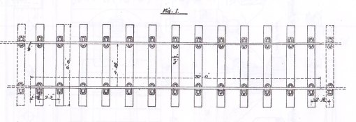
GWR plain track of the mid-1890s used 32ft rails of 92lbs per yard carried in cast iron chairs with 12 sleepers per rail length, except where the formation was soft, then an extra sleeper per rail length was introduced. Much of the ground in the vicinity of the the Inner Circle Extension, including Gun Street, was old marsh land, so naturally the GWR used 13 sleepers per 32ft rail throughout the sidings. Standard sleepers were 9ft long, of 10in x 5in section and made of Baltic redwood fir, the sleepers were treated with creosote before the chairs were fixed by fang bolts. The arrangement of a plain track panel with 32ft rails is shown below.
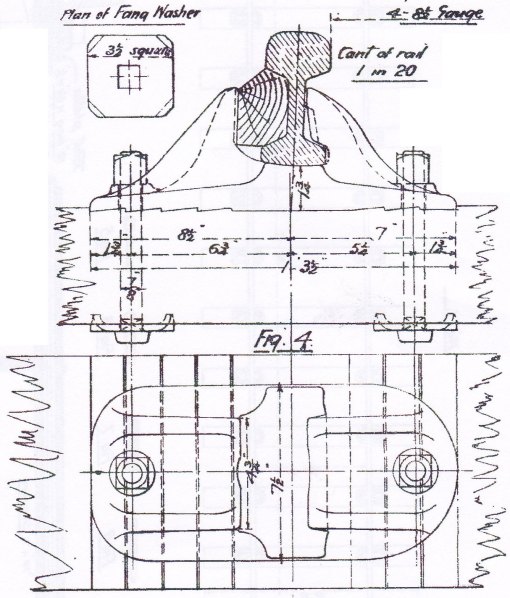
The GWR standard plain chair of the period was of cast iron and weighed circa 46lbs. Keys to retain the rail in the chair were made of oak or teak… and handed. A drawing of the standard chair, with fang bolts, nuts and washers, is shown below.
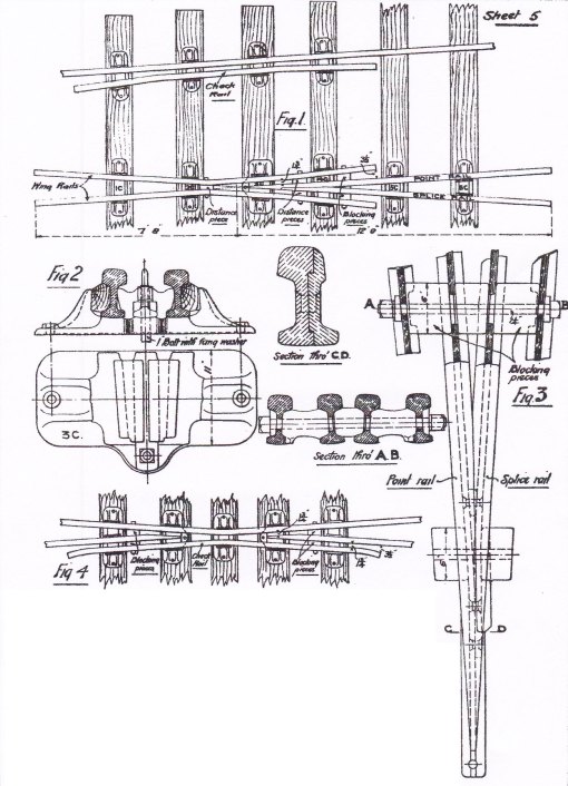
The arrangement of the common crossing for simple turnouts requires special chairs and fittings to hold the crossing vee and wing rails in alignment. The GWR had a range of special chairs for the various crossing angles and each chair type was used at a specific position relative to the crossing nose. In the 1890s those chairs were referred to as the 1C, 2C… 6C chairs although nomenclature changed later. At this time the chair under the crossing nose, referenced here as the 3C chair, was a casting – the nose of the vee slid into the casting and was retained by a vertical bolt through an extension of the nose. Some of the special chair types are shown below.
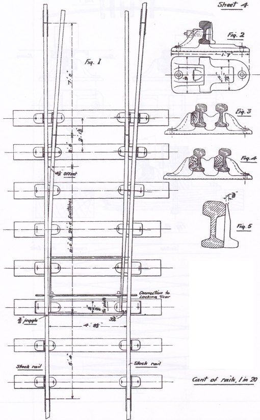
As with the range of common crossings with different crossing angles the GWR had a range of switches of different lengths. The switch rails varied in length according to the radius of the turnout… the greater the radius the longer the switch. In the period of Basilica Fields the switch blades were available in lengths from 9ft up to 20ft where the length is measured from the tip of the switch to the point at which the switch rail has attained the “4 1/2in offset” from the stock rail – the switch rail extends for 2ft beyond the “4 1/2″ offset” and the extra length is supported in the heel chair. The switches of a simple turnout are shown below.
The next part of this topic is to cover the construction of some plain track for the sidings and the catch point where the sidings join the Inner Circle Extension of the Metropolitan ‘Main Line’.
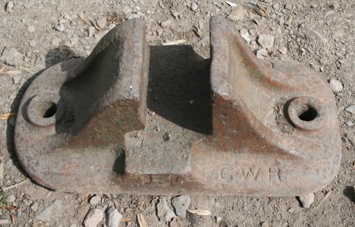
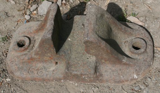
After publishing the first version of this post, and subsequent to the comment from Alan Woodward, I have been able to photograph an example of a chair as shown in Harvie’ s paper (drawing sheet 1, fig. 4 – illustrated above). Of interest given the comments on this post and on a recent Quirky Query is that the chair has recessed characters and the number “68” (which may refer to the “68d section”, 86lbs per yard, which was introduced in 1882).
May 3, 2011 at 4:29 pm
I have a GWR chair the same as in fig 4
The numbers and letters are cast into the chair as in your unusual chair. On one side at the flat? end it has GWR, on the other round? end same side is the letter N and on the flat end opposite the GWR it has 68 with a little D by the 8 or its G8 with the D. I have no clue as to what these numbers and letters meen. Any idea as to when raised letters and numbers came into use ?.
May 4, 2011 at 7:23 pm
The illustrations for this subject are taken from the GWR Engineering Society pamphlet no. 17… and the pamphlet has several “sheets” of illustrations. Each sheet contains several drawings and those drawings are noted as fig. 1, fig 2, etc.. There are several “fig 4” drawings in the pamphlet and the text refers to specific drawings by “sheet” and “figure”.
When editting the files for inclusion in this journal I removed the sheet identities… Alan is referring to the chair drawing on the second illustration of the post.
regards, Graham Beare
May 7, 2011 at 9:37 pm
Further to my earlier reply…. Bowler includes details of the Bullhead rail sections which were introduced between 1882 and 1900, those details include rail cross-sections, the reference by which the section was known by the GWR, and the date of introduction (see GWR PW for Artillery Lane – Part 1). Bowler gives the reference for the 86lbs rail of 1882 as “68d”… which is what Alan has found on his chair.
The respective cross-sections in Bowler show that the 86lbs rail had a foot which is smaller in width and depth than the succeeding 92lbs and 95lbs per yard rails (the 92lbs and 95lbs rails had an identical cross-section for the foot). A possible conclusion from comparing those sections is that a chair for the 86lbs rail did not accept the 92lbs / 95lbs rails (although 86lbs rail might fit in a chair for the 92lbs / 95lbs rail).
Harvie refers to the chair in figure 4 (see above) as the “standard” GWR chair and that attribution implies that the chair is the current design for the 95lbs rail of 1897 (and the 92 lbs rail of 1894). An alternative interpretation of “standard” is that Harvie was referring to the overall shape and features of the chair as shown in the drawing – in which case the possibility exists that the style of chair shown in the drawing was available for the 86lbs rail as well as the 92lbs and 95lbs rails (and marked appropriately to ensure that chairs and rail were matched).
After writing the original post and a subsequent Quirky Query I have been able to photograph a GWR rail chair which is of the type shown in fig 4 of the original post and which has the letters GWR and numbers 68 recessed into the top of the base. Those photographs have been included in an update of the original post.
regards, Graham Beare
May 10, 2011 at 10:00 pm
I have had an opportunity to photograph a rail chair which seems to be similar to the drawing shown in the original post. The photographs have been included in an update of the post.
regards, Graham Beare
May 18, 2011 at 2:25 pm
A description of the methods used for modelling the Permanent Way for Basilica Fields has been posted in the “modelling” category, (see here).
regards, Graham